-
Mining Engineering
Encyclopedia Arctica 2b: Electrical and Mechanical Engineering
Mining in Northern Climates
Unpaginated | Vol_IIB-0162
EA-I. (Howard G. Wilcox)
MINING IN NORTHERN CLIMATES
CONTENTS
Page Location of Mines 1 General Mining Features 2 Underground Mining 4 Placer Mining 6 Stripping 7 Thawing 8 Dredging 11 Other Types of Placer Mining 12 Bibliography 12
001 | Vol_IIB-0163
EA-I. (Howard G. Wilcox)
MINING IN NORTHERN CLIMATES
Location of Mines . ✓
Location of Mines . Mining in the Arctic and Subarctic will include practically all of
the placer-mining operations in Alaska, and these mines account for 75%
of the gold produced there. Tin, antimony, mercury, asbestos, jade, and
coal are also produced in the northern part of Alaska.The important radium mines at Great Bear Lake, the large Flin Flon
deposits containing copper, zinc, silver, and gold, the Yellowknife and
other important gold properties of the western provinces, the Hollinger
and other gold mines of Ontario and Quebec, the silver and cobalt mines
of the same provinces, and the gold-lead deposits of northern Labrador are
in the arctic or subarctic regions. The large iron ore reserves in north–
eastern Quebec and Labrador will be under subarctic conditions.Most of Siberia is included in the A a rctic- S s ubarctic region. ✓
Industrial enters, metallurgical plants, and mines have been opened on
a large scale on and near the Trans-Si l berian Railway at Novosibirsk and ✓
Irkutsk. In northeastern Siberia, gold was being mined in 66 districts
in 1940. The Kolyma River basin is the most important district. A road
extends north 400 miles from Magadan to Seimehan in the center of the
gold fields.
002 | Vol_IIB-0164
EA-I. Wilcox: Mining
Ferrous mines have been opened in the eastern Ural Mountains, and
coal from the Pechora coal field at Vorkuta is to be used to smelt iron
ores from the Kola Peninsula.The Petsamo nickel deposits in Finland, the Kiruna iron deposits in
northern Sweden, and iron, nickel, and coal deposits of Norway are all
mined in arctic or subarctic districts.It will be noted from the geographic location of the mines listed
that all are in the Northern Hemisphere, and that there is a wide difference
in latitude between the deposits. The southern boundary of the permafrost
area dips south of 50° N. latitude south of Hudson Bay in Canada, swings
north of 60° N. latitude in Alaska, then dips south of 50° N. latitude in
Siberia, and then goes north of 70° N. latitude in Sweden. Probably all
of the area north of this boundary may be safely classified as A a rctic or ✓
S s ubarctic and there are additional a reas south of the permafrost boundary ✓
that may be classified as S s ubarctic. ✓General Mining Features . ✓
General Mining Features . Mines that are developed in arctic or subarctic areas have permafrost
or substantial seasonal frost to contend with. In some localities this
may involve mainly constructing, insulating, and heating buildings to
make them suitable as living quarters, offices, mine entries, or shops.
i I n other localities the construction of dams, ditches, foundations of ✓
structures, and many phases of the mining operation may require special
knowledge and planning.
003 | Vol_IIB-0165
EA-I. Wilcox: Mining
Due to lack of adequate transportation facilities, the first minerals
mined are those that have high values compared to their weight, such as
gold and platinum. Also, they are mined by methods that require the mini–
mum amount of equipment. The adaptation of the airplane to arctic flying
conditions has greatly facilitated prospecting and mining. Cargo planes
are used for handling supplies and high-grade ores or concentrates, in
some instances at lower costs than similar freighting by “cat train”.
As the cheaper forms of transportation become available, the lower-grade
deposits are mined, and smelters are built to treat the base-metal ores.Mining may be classified as underground and open pit, or surface
mining. Placer mining is a specialized form of open-pit mining, in which
the values in gold, platinum, tin, etc., generally occur in loosely or
unconsolidated sand and gravel that under arctic conditions are usually
frozen. All muck and gravel that is frozen is not tightly consolidated
or held together by ice. The voids in the muck or gravel are not ice-filled
on benches or ridges that were above the ground-water level at the time the
ground was frozen. The term “dry frost” is often applied to frozen ground
that is not consolidated by ice. Where this condition exists, the muck can
be sluiced off practically as readily as unfrozen ground, and the gravels
can be mined without being thawed. The first seven years the United States
Smelting Refining and Mining Company operated the Cripple Creek dredge at
Fairbanks it mined in dry frost ground.
004 | Vol_IIB-0166
EA-I. Wilcox: Mining
Placer deposits can be worked at a lower cost per yard or ton than
underground mines; and the cost of equipping a placer mine is less than
for an underground mine of similar size. Consequently, placer mining is
generally the first type of mining initiated on the fringes of civilization.
As roads, railroads, and airfields are constructed in the new placer-mining
districts, development of gold lode mines and base metal mines follows.
The mining of heavy-tonnage material like iron and coal requires relatively
low-cost mining and transportation.The use of Eskimo labor has proved advantageous in the Seward Peninsula
and Kobuk River districts in Alaska. The natives have been used as point
drivers in the thawing operations, and some of them are good semiskilled
workmen and are used as “cat” drivers, shovel operators, and winchmen on
the dredges.The cost of mining is greater in arctic and subarctic regions, due to
higher transportation rates, material and labor costs, mining or preparation
costs, and in many places seasonal operations.Underground Mining . Underground mining may be carried on the year
round if a continuous supply of water and fuel is available, properly
insulated buildings are constructed, and surface plant and mining methods
properly planned. Underground mining in a permafrost district does not
involve unusual mining problems. Shattered frozen ground requires less
support than thawed ground of similar nature. The supplying of water to
the working faces may require special precautions, and the ventilation should
be planned so the main working shaft will not be upcast, as ice will form
near the collar and interfere with hoisting. Where permafrost is present
the deeper workings are generally below that area.
005 | Vol_IIB-0167
EA-I. Wilcox: Mining
The disposal of camp sewerage or drain ing age water from the mine may ✓
require special consideration. Water that flows at a low velocity will
“glacier.” The water freezes in one channel and then breaks out into a
new channel. This process is repeated until a large area is covered with
ice and may reach the camp area if provisions to prevent “glaciering”
have not been made or the discharge carried to a safe distance.Small-scale gold lode mines are operated the year round in perma–
frost near Fair w b anks, Alaska. Large-scale underground operations in ✓
arctic ground are conducted in northern Canada, Siberia, Finland, Sweden,
and Norway. Underground and opencut coal mines are operated on a yearly
basis in Alaska and other countries within the permafrost regions. Open–
cut mining can be carried on, as far as mining operations are concerned,
at any time of the year, but it may be uneconomical to mine when weather
conditions are too severe during the coldest weather or when thawing
occurs during the spring breakup. At the Alaskan opencut coal mines,
stripping of the overburden is accomplished by hydraulic methods in the
summer season, and stripped ground is mined at any time during the year.
Coal can be mined more advantageously near high banks in the winter when
the ground is frozen and no sloughing occurs.
006 | Vol_IIB-0168
EA-I. Wilcox: Mining
Placer Mining . Extensive placer-mining operations are carried on
in Yukon Territory in northwestern Canada, central and western Alaska,
and in northern and northeastern Siberia. Gold is the principal mineral
mined, but minor amounts of platinum, tin, rutile, and jade are also
recovered. Siberia at one time was the leading producer of platinum
minerals. In Alaska, limited amounts of cassiterite and jade are being
recovered from the Seward Peninsula and the Kobuk River areas.Most of the placer deposits in the Arctic were laid in the preglacial
or Pleistocene era, and the principal placer-mining areas are in nonglaciated
regions. Active glaciers were prevented from forming in the Dawson district
in Canada, in the Yukon and Kuskokwim River basins in Alaska, and in northern
and eastern Siberia, not because of warmer temperatures, but because of
insufficient precipitation. Active glaciers in these regions would have
scoured out the valleys, and the gold previously concentrated in the stream
beds would now be disseminated throughout a vast quantity of glacial till
and outwash. The gold content in streams in glaciated regions is generally
too limited in extent or low in value to be minable. There are exceptions
in instances where glacial outwash material has covered undisturbed preglacid
deposits, as at Nyac in Alaska, and where there have been areas covered by
ice that did not have enough force to erode all of the preglacial deposits
as in the Sache Creek district in Alaska.The finding of mammoth, mastodon, saber-toothed tiger, and camel
bones at or near the top of gravel is common. Some of the bones have
marrow in them, and sinew, hide, flesh, and hair often cling to them.
Animals lived in the ice-free areas during the early part of the glacial
period, and their bones remain in the valleys in which they died, because
there has been no glacial action to carry them away.
007 | Vol_IIB-0169
EA-I. Wilcox: Mining
Stripping . The placer gravel is covered by overburden that varies
from a few feet to 200 or more feet in depth. This material is very fine
and often contains considerable vegetable matter. The common term applied
to it is muck, and it is removed in the preparatory state of a placer
operation that is called stripping. Most of the muck is frozen and often
contains ice lenses, and where there are considerable quantities to be
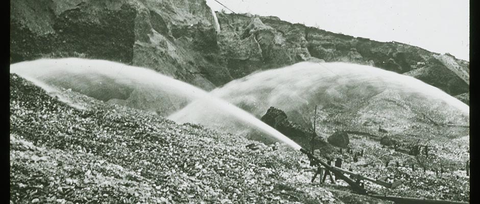
removed hydraulic methods are employed. First moss and timber are removed
by bulldozer or nozzle. Bulldozers can be used before the thaw has pene–
trated too deeply. Nozzles are set up in the area to be stripped and are
spaced so that the radius of the stream from one nozzle will meet the stream
spaced so that the radius of the stream from one nozzle will meet the stream
from the adjacent nozzle. Stripping is done in the summertime. The heat of
the sun thaws about 4 in. of muck in the first 24 hours , 2 to 3 in. the ✓
second day, and progressively loss on succeeding days. One nozzlemen will ✓
take care of about 6 nozzles. He washes off the thawed fine material from
the area in front of one nozzle, and then goes on to each succeeding nozzle
to perform the same operation. About 2 in. of thawed much is swept away
from each station every shift, and the sluicing is carried on 24 hours a
day. The hydraulic water is generally brought in ditches that reach the
stripping area 100 ft. or more vertically above the nozzles. The thawed
material is carried off below the mining area in previously prepared drains
that require a low gradient due to fine particle size of the suspended
material.
008 | Vol_IIB-0170
EA-I. Wilcox: Mining
The amount of material that can be stripped by a unit of water is
called the water duty. This is expressed as cubic yards removed per miner’s
inch. In Alaska a miner’s inch is 1½ cu. ft. of water per minute. This
amount of water flowing for 24 hours is one miner’s inch daily (MID). Ten
to fifteen cubic yards of much removed in 24 hours by one miner’s inch
would be within normal limits. A medium-sized ditch would carry 1,000
miner’s inches; with a water duty of 15, the water available would strip
15,000 cubic yards of much in 24 hours. The cost of stripping varies at
different placer operations in Alaska. The cost, in 1949, is probably
between 6 and 10 cents a cubic yard.Thawing . Most of the gravels in the Arctic or Subarctic are frozen,
and when frozen must be thawed before they can be mined (Fig. 1). Various
methods of thawing have been tried, but the cheapest method and the one that
is used at most properties is cold-water thawing. Steam points are used in
drift mining and in special cases for small patches of ground that are
delaying dredging (Fig. 2).For ground of average depth, 10 to 30 ft., the thaw points are spaced
on 16-ft. centers. For deeper ground the points may be spaced on 32-ft.
centers and in shallower ground they may be on 8- or 12-ft. centers. The ✓
water is brought to the thaw field in 14- to 18- in. slip - joint hydraulic ✓
pipe. This is distributed by 8- to 12- in. flanged feeder pipe at 27½-ft.
intervals; 6-in. slip-joint header pipe is laid across the thaw field.
On long runs this 6-in. slip-joint header pipe is laid across the thaw field.
On long runs this 6-in. slip-joint pipe is reduced to 4 in. on the outer
end. One inch hose connections are tapped into the feeder pipe and a hose
brings water under 10 to 15 lb. pressure, to a gooseneck at the top of the
thaw pipe. A chisel bit with water outlets on both sides is attached to
the bottom of the pipe.
009 | Vol_IIB-0171
EA-I. Wilcox: Mining
The water thaw begins around the pipe and progresses as a cone-shaped
area, with the apex on bedrock, until the cones coalesce at the surface
and the thawed area begins to assume the shape of a cylinder. The points
remain in the ground until all the gravel is thawed (Fig. 3). The ground
is tested by driving a steel bar to bedrock midway between thaw points.
t T his is called probing. Then the area is thawed, the points are pulled, ✓
and a new thaw field is established.The thaw points had all been driven manually until the United States
Smelting Refining and Mining Company developed at Fairbanks an electrically
operated mechanical driving mechanism in 1946. The mechanical driver will
eventually replace the manual driving where electricity is available.Points are driven mannually by sliding a weight (the hammer) up and ✓
down the pipe and striking a piece of metal that is clamped to the pipe
(the anvil). One man may take czre of 50 points by attaching the anvil
and hammer to each pipe in succession and driving the point to frost.
It may take a few hours to make the complete circuit, and at each point,
3 or 4 in. of gravel has thawed below the point before the driver returns.
The point is driven through the thaw to the frozen ground; it cannot be
economically driven into frozen material. An individual point is seldom
driven more than 1 or 2 ft. in a day.
010 | Vol_IIB-0172
EA-I. Wilcox: Mining
The amount of thawing accomplished depends upon the amount and
temperature of the water used. Each point requires 0.5 minter’s inch
of water. The available heat in the water is the difference between the
temperature of the water and 32°F. When thawing water is recirculated
in the summertime or is taken from long ditches, the temperature may be
50°F. or more at the time it enters the ground. When the water tempera–
ture is 38°F. in the spring or fall, the temperature of the water return–
ing to the surface may be 34°F. Then only 4 degrees of hest have been
transferred to the gravel and thawing would be very slow. Four months is
the maximum thawing season in interior Alaska. In 1949, thawing costs
ar ranged from 6 to 12 cents a cubic yard. ✓Under favorable conditions, which is shallow ground that is 10 to
20 ft. deep and that has fairly open gravel free of sand lenses, natural
thaw can be used. The overburden is stripped from the gravel three years
before the ground is dredged, and in that time the gravel and the upper
foot or two of bedrock will become thawed. Winter frost will penetrate
5 to 7 ft. into the ground, but this ground will be thawed by about the
middle of June. The only water thawing necessary where natural thaw has
taken place is to thaw sufficient ground for dredging before the middle of
June, at which time the winter frost will have disappeared.
011 | Vol_IIB-0173
EA-I. Wilcox: Mining
Dredging . The bucket-line floating dredge (Fig. 4) is a standardized
piece of equipment and, where conditions are suitable for dredging, it
recovers gold at the lowest cost of the same method of placer mining.
General conditions in the Subarctic are similar, and there are the additional
features of seasonal frost, insulating and heating the dredge, and
thawing of ice from ladder, lines, etc. the dredging season for small
dredges with limited water supply may extend from June 1 to October 15.
The larger dredges in deeper ground and with sufficient water may operate
8 months a year. Dredging of frozen ground is not attempted by any well–
informed operator. The dredging mechanism will not stand the strain, and
gold in frozen gravel passes through the boat and onto the tailings pile.Due to the short season, dredges are put in good operating condition
before the season begins, and a large stock of parts is carried. A high
percentage of operating time is essential when seasons are short. The
financing of relatively large inventories, which must be bought a year
ahead, and high freight rates substantially increase mining costs. Dredg–
ing costs in Alaska for the smaller operator are figured at 20 cents a
cubic yard, stripping costs at 10 cents, and thawing costs at 10 cents,
a total of 40 cents a cubic yard. The cost for the large well-organized
and financed operation is substantially below this figure.
012 | Vol_IIB-0174
EA-I. Wilcox: Mining
Other Types of Placer Mining . In the past 10 or 15 years many
small mechanized placer operations employing 8 to 25 men have started
mining in Alaska, and this type of operation is being adopted in Canada.
Mechanized methods are used in small stream deposits, on the benches, or
where bedrock gradient is too steep to dredge. Elevated sluice boxes
are mounted on trestles that are built on skids and can be moved by
tractors. Draglines are used to feed the gravel into a dump box at the
head of the sluic d e and a bulldozer is used to keep the tailings pushed ✓
away from the discharge and. A bulldozer is also used to clean bedrock
and shove the material to the dragline. Sluice boxes are also set in
bedrock and, where water is limited, a tractor-mounted bulldozer pushes
the gravel to the mouth of the sluice, and a nozzle, which is often supplied
with recirculated water, washes it into the box. The tailings that accumu–
late at the lower end of the box are removed by bulldozer, drag scraper,
or dragling. These operations, in which modern dirt-moving practices
are used in placer mining, have made possible the mining of numerous de–
posits that would otherwise be unworked.
BIBLIOGRAPHY
1. Engineering and mining journal . N.Y. vol.1, 1866-
2. Western miner . Vancouver, B.C. vol.1, 19 ? -
3. Mining world , with which is combined Pacific chemical and metallurgical
industries . Seattle, (etc.) vol.1, July, 1939-4. Muller, Siemon. Permafrost or Permanently Frozen Ground and Related
Engineering Problems . Ann arbor, Mich., Edwards, 19 4 47 . —5. Peele, Robert, ed. Mining Engineers’ Handbook . 3d ed. N + . Y + . , Wiley,
1941. 2v.Howard G. Wilcox
Prospecting and Exploration of Minerals in the Arctic and Subarctic Alaska
Unpaginated | Vol_IIB-0175
EA-I. (Robert S. Sanford)
PROSPECTING AND EXPLORATION OF MINERALS
IN THE ARCTIC AND SUBARCTIC ALASKACONTENTS
Page Introduction 1 Geophysics 2 Prospecting Methods 3 Tracing Float 5 Trenching 5 Test Pits and Prospect Shafts 5 Hydraulic Prospecting 6 Booming 6 Drivepipes 6 Piercing or Probing 7 Vegetation 7 Burrowing Animals 7 Boring 7 Permafrost 13 Transportation 15 Coal Exploration 17 Outfitting of Personnel 21 Bibliography 23
Unpaginated | Vol_IIB-0176
EA-I. Sanford: Prospecting and Exploration of Minerals
LIST OF FIGURES
Page Fig. 1 Diagram to show tools and drilling operations of
Hillman airplane placer drill9-b Fig. 5 Construction details for canvas boat 17-a
Unpaginated | Vol_IIB-0177
EA-I. Sanford: Prospecting and Exploration of Minerals
PHOTOGRAPHIC ILLUSTRATIONS
With the manuscript of this article, the author submitted 7
photographs, Figures 2 through 4, 6 through 9, for possible use as
illustrations. Because of the high cost of reproducing them as halftones
in the printed volume, only a small proportion of the photographs sub–
mitted by contributors to Volume I, Encyclopedia Arctica , can be used,
at most one or two with each paper; in some cases none. The number and
selection must be determined later by the publisher and editors of
Encyclopedia Arctica . Meantime all photographs are being held at
The Stefansson Library.
001 | Vol_IIB-0178
EA-I. (Robert S. Sanford)
PROSPECTING AND EXPLORATION OF MINERALS
IN THE ARCTIC AND SUBARCTIC ALASKAINTRODUCTION
The necessity for thoroughly prospecting a mineral deposit cannot be
too strongly emphasized. Many failures in mining are due to a lack of
careful prospecting or to incorrect interpretation of the results. The
irregularity of gold distribution in Alaska alluvium makes careful pros–
pecting necessary in order to trace the limits of the pay streak.Contrary to popular belief, the Arctic is not bleak and dangerous.
True, the early explores, prospectors, and miners did suffer many hard–
ships, but this was frequently due to inadequate knowledge and preparation.
The work of Stefansson and others has proved that, with proper knowledge,
adequate preparation, and suitable, well-chosen equipment, exploration can
be conducted in the Arctic with a minimum of danger and hardship.In the Arctic, some phases of prospecting can be done at all times of
the year. Winter is often the best season; in fact, many companies do most
of their exploratory drilling from February to May, inclusive. Heavy drills
can be readily moved across marshy areas without miring, and it is easy to
drill a stream bed from ice. Likewise, test pitting can be done best during
the winter, especially in wet deposits.
002 | Vol_IIB-0179
EA-I. Sanford: Prospecting
All of the tools and supplies of the prospector, the mining engineer,
and the geologist can be used in the Arctic, and some can be used to better
advantage in permafrost (permanently frozen ground). The more important
of these are the pick, shovel, dynamite, gold pan, drivepipe, churn drill,
core drill, hand drill, compressed-air drill, bulldozer, power shovel with
trench-hoe attachment, dip needle, and geophysical instruments, including
the Geiger counter.Ordinary prospecting, exploration, and development methods have been
described in detail in mining literature and are discussed only briefly in
this article. Arctic conditions have changed or modified certain of the
methods, and these will be discussed in greater detail.Geophysics is the art of applying the physical sciences to the study
of the structure and composition of that part of the earth that is suffi–
ciently near the surface to be exploited by man (4,5,11). The earth’s
surface has been fairly well prospected for outcrops of ore bodies,
petroleum seepages, and gas bubbles on water. Many of the easily located
deposits have been found and are being exploited. The increasing demand
for metals and oil contributed to the development of geophysics. Geo–
physical methods have been more successful in the exploration for oil than
for metals (4). According to Jakosky (5), “During the entire life of the
American petroleum industry an average of about 180.000 barrels of oil have
been discovered for each dry hole drilled. During the past three years
(1937-1940), with geophysical exploration as a guide in a large portion
of the wells drilled, discovery of oil has been at the rate of about
300,000 barrels for each dry hole.”
003 | Vol_IIB-0180
EA-I. Sanford: Prospecting
The most noteworthy recent advance in geophysical exploration has been
the development and use of air-borne magnetometers. Four different types
are either being used or are under construction. Two are modifications of
the “magnetic air detector” developed by the Navy during the war to assist
in locating submarines. Both have such sensitive pickup units that the
pickup must be towed 100 to 200 ft. from the airplane to avoid the dis-turb–
ing influence of the plane itself. Ground correlation is secured by means
of terrain photography, using a continuous strip camera, or by radar
triangulation.Han e s Lundberg has built a helicop t er-borne magnetometer and is able
fly close to the ground and secure greater detail than from a conventional
airplane.The U.S. Geological Survey reports that during 1946 more than 50,000 sq.mi.
was covered by aeromagnetic surveys, including surveys of Naval Petroleum
Reserve No. 4 in arctic Alaska, the magnetic-iron region in New York State,
and potential petroleum-producing areas in several states and offshore
portions of the Gulf Coast.Aerial P p hotography is an invaluable aid in mapping, and such maps are
useful to the prospector and engineer. It is sometimes possible to trace
poorly exposed outcrops and faults on aerial photographs. (Since 1939, the
U.S. Air Force and Navy have mapped the larger part of northern Alaska by
aerial photography.)PROSPECTING METHODS
The search for minerals is guided by knowledge of geological associations.
The presence of mineral outcrops warrants prospecting to determine whether
shoots of commercial ore exist. The presence of float, (pieces of ore,
minerals, or metals) also justify prospecting. Favorable geological associa–
tions and characteristics must be studied carefully and an effort made so
avoid useless work in unfavorable locations.
004 | Vol_IIB-0181
EA-I. Sanford: Prospecting
Placer deposits may be classified according to origin, as residual,
sorted, and resorted. Brooks classifies Alaska placers, based on position
and form, as follows (1):Creek placers: Ground deposits in beds and intermediate flood plains of
small streams.Bench placers: Gravel deposits in ancient stream channels and flood plains
which stand from 50 to several hundred feet above the present streams.
Hillside placers: A group of gravel deposits intermediate between the
creek and bench placers. Their bedrock is slightly above the creek bed,
and the surface topography shows no indication of benching.River-bar placers: Placers on gravel flats in or adjacent to the beds
of large streams.Gravel-plain placers: Placers found in the gravels of the coastal or
other lowland plains.Sea-beach placers: Placers reconcentrated from the coastal-plain gravels
by the waves along the seashore.Ancient beach placers: Deposits found on the coastal plain along a line
of elevated beaches.Lake-bed placers: Placers accumulated in the beds of present or ancient
lakes that were generally formed by landslides or glacial damming.Surface methods consist of tracing float ore by panning, trenching,
and test pitting. Continuing the investigation of ore bodies at depth
and search for minerals that do not outcrop are done by physical methods,
such as boring, shaft sinking, or diving adit tunnels.
005 | Vol_IIB-0182
EA-I. Sanford: Prospecting
Tracing Float . Pieces of ore (float) are separated from the vein
by erosion, work their way downhill into steams, and may be carried long
distances. The prospector finds the float and tries to follow it back to
its source. The placer miner’s gold pan is a valuable tool in this work.Trenching . After an ore occurrence has been found, its surface limits
may be determined by trenching. The first trenches should be rather far
apart; this generally reduces the number, length, and cost of intermediate
trenches. On the other hand, trenches should be close enough to avoid
missing ore shoots and to determine average width and value. After the
direction of the strike of a narrow ore body has been determined by two
cross trenches, it is often more satisfactory to trench along the strike.Trenches may be excavated by hand, but often it is cheaper to use a
bulldozer or power shovel with a trench-hoe bucket. When permafrost is
encountered, the Alaska prospector does not try to fight the frozen ground,
but starts another trench and allows the sun to melt the frost in the first.
By excavating several trenches in turn, fair progress can be made.Test pits and prospect shafts are used where the soil is too deep for
trenching. For systematic exploration, the pits are located on corners of
squares, or along lines across the pay streak of a placer deposit. The
outfit for sinking in permafrost consists, at least, of a 4-hp. boiler,
steampipe, hose, drive points, and windlass. Some miners thaw only a few
feet at a time, as the pit is deepened. Other miners drive the pipe slowly,
steaming the ground 30 to 45 minutes per foot of depth, and adding lengths
of pipe as needed until the bedrock is reached. During the summer, water
at natural temperatures can be used for thawing.
006 | Vol_IIB-0183
EA-I. Sanford: Prospecting
Test pits can be sunk in shallow ground by thawing with wood fires.
As thawing is slow, several pits should be sunk simultaneously. Test
pits can often be sunk in shallow, wet ground during the winter by
“freezing down.” The pits are dug to water level and allowed to freeze.
The frozen material at the bottom of the pit is removed until water is
again reached, and the process repeated until bedrock is reached. This
method is slow, but one miner can handle several pits, and it is generally
cheaper than other methods of sinking through formations saturated with water.When thawing mercury-bearing ground, to avoid sal v i t v ation or mercury
poisoning, adequate ventilation must be provided.Hydraulic Prospecting . Where water is available, during summer operations,
hydraulicking is a great aid in stripping soil for close examination of bedrock.
Sometimes a small stream can be diverted in a ditch along the hillside above
the area to be prospected. A small pump and several hundred feet of canvas
fire hose have been used to advantage in washing the soil off bedrock.Booming . In summer, when the water supply is limited, a reservoir can
be excavated or a dam built. After the reservoir is full, the water, when
suddenly released, rushes down the hillside and strips the surface soil.
Booming is also used in placer mining. Automatic gates that open when the
water reaches a certain depth are useful in booming.Drivepipes have limited use in soft soil or fine gravel free from
large stones or boulders. Pipes are 1 to 3 in. in diameter. The perimeter
of the bottom end of the pipe is filed to a cutting edge, and a slot of
about 0.25 in. wide and 4 ft. long is cut in the pipe. The slot aids in
gripping the soil and facilitates cleaning the pipe. The pipe may be
churned down by hand or driven with a maul. The upper end of the pipe
should be protected by a cap while driving. Short lengths of pipe are
screwed on as the hole deepens. The pipe is pulled every foot or two and
the contents examined.
007 | Vol_IIB-0184
EA-I. Sanford: Prospecting
Piercing or probing with pointed steel rods with a small slot or recess
in the point is a method used in searching for minerals lying at shallow
depths. The mineral or vein sought is either harder or softer than the sur–
rounding material, or possesses a characteristic color which can be deter–
mined by the probe.Vegetation often grows thickly along outcrops of one geological
formation and sparsely on another. For example, the soil derived from
weathered dunite is not fertile, and hence it is easy to trace the outcrop.
Dunite is often the host rock for chromite ore.Burrowing animals often aid the prospector by the debris they throw
out when digging holes.Boring for prospecting, exploration, and development is done with hand
augers, core drills, and churn drills. The purpose is to locate mineral
deposits covered by soil, rock, swamp or water; to determine their length
and depth; and to search for parallel ore bodies. While the size and
shape of an ore body are being determined, representative samples should be
obtained so that an estimate of tonnage and grad s e can be calculated.Posthole augers have been used for sampling shallow tailing dumps and
various types of unconsolidated mineral deposits. In 1942-43, Bureau of
Mines engineers used hand augers , 3 in. in diameter, to sample large deposits
of high-alumina clay (10). Three hundred and sixty holes were drilled,
aggregating 14,938 ft; more than 50 of these holes were over 80 ft. deep.
It is seldom feasible to drill so deep with hand augers, and only under
exceptional conditions does an auger yield reliably accurate samples.
It is most useful for preliminary testing of shallow deposits.
008 | Vol_IIB-0185
EA-I. Sanford: Prospecting
A core drill consists of the boring column and the surface power plant.
Core drills are built in sizes from the small prospect drill with a drilling
depth capacity of 100 feet, easily carried by two men, to large, diesel–
powered machines that will drill to a depth of over 10,000 feet. The
boring column consists of a bit set with diamonds that is rotated under
pressure; the reaming shell, also set with diamonds, that maintains the
size of the hole; the core barrel that hol e d s the core while drilling; and
the drill rods in 5- and 10-ft. lengths. Power may be provided w e ither by
gasoline, compressed air, steam, or diesel engine. The engine is coupled
either to a differential-gear screw or to a hydraulic fee t d with bevel gear
that rotates the boring column and feeds it ahead. A pump is required to
circulate the drilling water that cools the bit and brings the cuttings or
sludge to the surface.Core drilling has a number of advantages, as follows:
- (1) In rock a complete cross-sectional sample of the formation pene–
trated is obtained. The core can be split longitudinally, half sen d t for
chemical analysis and half retained for a permanent record. - (2) Holes can be drilled at any angle: down, horizontal, or up.
In cold climates the water pipelines must be protected against freezing,
and it may be necessary to preheat the water. When drilling in permafrost,
the rods must be kept in motion and the water circulating; otherwise, the
hole will freeze and the rods, core barrel, and bit will be lost. Low–
freezing cooling solutions to take the place of water have been used
successively, but they require special recir c ulating equipment and the loss
of liquid in porous or fissured ground is costly.
009 | Vol_IIB-0186
EA-I. Sanford: Prospecting
The objective of diamond core drilling is to recover samples to be used for
chemical analysis, physical tests, or visual inspection (9). Unless the samples
are reliable and the information systematically recorded, the time and money spent
in securing them are largely wasted. The diamond-drill sample consists of two
parts: the core (or cylinder of rock) cut out by the diamond bit, and the sludge
(or cuttings) group up by the abrasive action of the diamonds. There is often
excess sludge caused by the rubbing of core against core, or core against the core
barrel, or by the erosive effect of the core barrel against the side of the hole
and circulating water, or by caving from the upper part of the hole.If it were always possible to obtain complete recovery of core, the sludge
sample would not be important. In a soft, broken formation, it is impossible to
save 100 percent of the core. It is obvious that the importance of the sludge
sample increases as the core recovery drops. A new core barrel has recently been
developed, in which the inner tube is suspended by a ball-bearing coupling and
does not rotate with the barrel. It is designed to minimize mechanical friction
and water erosion of the core inside the bit and the inner tube. Thus, better
core recovery is obtained.The portable churn drill consists of several tools, among which are drill
bit, drill stem, jars and rope socket, and a gasoline, diesel, steam, or electric
power plant. Hand-operated churn drills sometimes are used in low-wage areas for
shallow holes, but seldom in the Arctic. The airplane-type churn drill is light,
rugged, and extremely portable. It was originally designed for a placer prospecting
drill, but has been used to explore completely many shallow softer ore deposits.
009a | Vol_IIB-0187
EA-I. Sanford: Prospecting
(see Fig. 1). The drill is designed with a 4-in. casing, using 5 1/4-in. drive
shoe, for drilling to a depth of 50 feet., or with a 5-in. casing and a 61/2-in.
drive shoe to a depth of 35 ft. the weight of the drill, with a 3-hp. gasoline
engine, is 1,600 lb. the drilling column weighs 300 to 400 lb. the drill can
be easily disassembled and carried in a small airplane, or on a dogsled.
009b | Vol_IIB-0188
Figure 1.
010 | Vol_IIB-0189
EA-I. Sanford: Prospecting
The airplane drill with a 3-hp. gasoline engine costs $1,340 . ; the same ✓
drill with a 6-hp. gasoline engine costs $1,560. In addition, drill column,
tools, tool-dressing outfit, casing, and miscellaneous equipment will cost
about $700 . (1948 prices). ✓Larger churn drills are available, suitable for all types of mounting,
such as skid, wheel, trailer, truck, or caterpillar. Caterpillar-mounted
churn dills will move rapidly over almost any ground. Certain caterpillar–
mounted drills are designed for a ground pressure of only 3.2 pounds per
square inch of track area. The ground pressure for a man is about 5 pounds
per square inch, and this unit will travel where a man is unable to walk.
A churn drill with rotary attachment is also available; it is able to churn
down a hole through unconsolidated overburden. The rotary attachment can be
swung into position and a core taken of the solid formation.A skid-mounted churn drill with a 30-ft. derrick costs $3,250. Mounted
on a caterpillar crawler it costs $5,506. In addition, tools, casing and
placer testing equipment will cost about $1,600 (1948 prices).Briefly, the drill is operated as follows. The drill is placed in the
desired location, leveled, and the derrick raised. Great care must be
exercised in assembling the tools to see that all joints are b t ight. A ✓
16-in. hole is dug. A drive shoe is threaded on one end of the casing and
a drive head on the other. The pipe is placed in the hole and dirt packed
around it. Tools are lowered, allowing the bit to enter the casing, and
the drive clamps are bolted on the bit. The engine is started and the
casing tapped into the ground. Lengths of casing are added as needed and
driven to gravel or permafrost.
011 | Vol_IIB-0190
EA-I. Sanford: Prospecting
Water is poured into the casing, the drill started, and the rock chopped
up. In testing placer ground, it is always customary to try to drive the
casing ahead of drilling. Three or four inches of cuttings are always left
in the casing to form a plug. When boulders are encountered, it is necessary
to drill below the drive shoe. A rock bit should be used in place of the
placer bit. The water level in the casing should be at least as high as the
water plane in the ground to prevent minerals from being carried into the
casing.The drill column is washed as it is hoisted out of the hole to remove
all mineral that may cling to the tools. The sand pump, with a sand line
attached, is lowered into the hole. The suction-type sand pump must be
raised rapidly to create a vacuum to suck in the sand, mud, and minerals.
It is common practice to pump before and after diving. The height of
cuttings in the casing is checked and recorded. The drive clamp is bolted
on, and the operations are repeated. After the hole has been completed,
the casing is pulled. The driv ing e head is removed from the casing. The ✓
knocking head is slipped over the puling jar, and the rop e socket is attached ✓
to the pulling jar that is lowered into casing. The knocking head is screwed
on the top casing and the casing is jarred up.
012 | Vol_IIB-0191
EA-I. Sanford: Prospecting
To evaluate the churn-drill sample, the pump is hoisted out of the casing,
and the contents are dumped into the mud box. The pump is washed inside and
out to remove all minerals. Thomas describes the method of evaluation placer–
tin samples at a Bureau of Mines project as follows (15):“The character of materials drilled and depth of each change in
material were recorded. When practical, 2-foot samples were taken in
barrel overburden and upper gravels, and 1-foot samples were collected
in the tin and gold horizons. Each sample was deslimed, measure loose
in a volume bucket, and panned. Concentrates from the panning of each
sample were put in separate jars, labeled as to depth, number of hole,
and line, and brought to a central point at the close of each shift.“Each individual sample was then panned, the gold extracted by
amalgamation and weighed, and the concentrates tested for the presence
of tin by the zinc method, examined with a hand lens, and weighed. The
individual samples from one hole were then combined and labeled to form
one sample of tin concentrates and one sample of gold.“All holes were drilled into bedrock for at least 2 feet, and some
were drilled deeper, depending on the amount of heavy concentrate found.“Open holes were drilled in frozen ground. The procedure of
sampling and recording the formations was that used in thawed ground,
except that after completing the hole a volumetric water measurement
was made to determine the size of the hole in the mineral-bearing horizon.“Each deslimed sample was measured to the nearest thousandth of
a cubic foot. The percentage of solids in the mineral-bearing horizon was
determined by using the sum of the total measured volumes loose and the
volume of the hole as determined by the water measurement.”Later a composite of the tin concentrates was made and assayed for
metallic tin.
013 | Vol_IIB-0192
EA-I. San d ford: Prospecting —
PERMAFROST
Permanently frozen ground is widespread in the Arctic and Subarctic.
The expression “permanently frozen ground” is cumbersome, and a shorter
term, “permafrost,” is in general use as an alternative. Permafrost occurs
in northern Asia, in most of Alaska, and in northern Canada. Nearly one-fifth
of the land area of the lead area of the world is underlaid by permanently ✓
frozen ground. The southern limit of permafrost roughly coincides with the
30°F. isotherm. Along the southern fringe, most of the ground is unfrozen
but contains islands of permafrost. To the north, areas of permafrost will
have islands of unfrozen ground. Continuous permafrost with prevailing
ground temperature below 28°F. exists still farther north.The temperature of permafrost, at depths of 10 ft. or more, remains
nearly constant summer and winter. Permafrost must not be confused with
ground frozen by low winter temperatures or “seasonally frozen ground.”Stresses developed in permanently frozen ground may exceed 6,000 pounds
per square inch, and it is not feasible to meet such stresses by structural
design alone. It has been demonstrated that satisfactory results can be
achieved if the dynamic stresses of frozen ground are analyzed and structures
designed accordingly. A systematic and comprehensive study of frozen ground
should be an integral part of the planning and design of all engineering
projects in the Arctic.Permafrost is a handicap to hand trenching and bulldozer trenching.
It does not interfere with diamond drilling, except that drill water must be
kept circulating, and drill rods should never be left in the hole after the
pump has stopped. Permafrost has made churn-drill exploration for placer gold,
tin, and platinum very nearly an exact science.
014 | Vol_IIB-0193
EA-I. Sanford: Prospecting
Permafrost interferes, to a certain extent, with opencut mining and
surface placer mining. Overburden must be thawed and stripped, and the
gold-bearing gravel thawed before mining operations can begin.To balance these disadvantages, permafrost often may aid the miner.
Livengood Placer, Inc., has constructed an earth dam with a permafrost core.
Earth was sluiced into place during the summer and frozen solid the next winter.
This operation was repeated for several years, adding to the height of the dam.
A minimum of labor was required. Only the last lift of earth was placed with
carryalls.The U.S. Smelting, Refining, & Mining Co. has stabilized muck banks at
a very steep angle by maintaining the permafrost in the muck. Pipes for cir–
culating the freezing solutions are installed in drill holes. The freezing,
at depths below the seasonal freeze, usually is done during the winter. The
solution is pumped through a radiator and chilled by the air in the winter,
and it is not necessary to use artificial refrigerat or ion except in the summer. ✓The same company is dredging a pay streak along one side of wide
Chatanika Valley. Permafrost has made this possible. Bedrock goes down
steeper than the valley floor. To dredge bedrock, a very large, deep-digging
dredge would have to be purchased, or the water level in the dredge pond
could be lowered below the valley floor by pumping and thus permit digging
bedrock with an available dredge, provided the inflow was not too great.
The flow of the two streams that enter the valley was measured and the cost
of pumping calculated. This was found to be economical because permafrost
kept out seepage from the wide valley.Permafrost does not handicap underground mining operations in hard rock.
All that is needed is to protect water pipelines against freezing and provide
other cold-weather protection.
015 | Vol_IIB-0194
EA-I. Sanford: Prospecting
TRANSPORTATION
Except for increased costs, there have been few changes in ocean,
rail, and river transportation during the past few years. In the Arctic
and Subarctic, the caterpillar tractor and sled have taken the place of the an
animal-drawn freight wagon and sled, and airplanes have become indispensable.Winter freighting with caterpillar tractors to all isolated communi–
ties is common practice (Fig.2). A train of heavy-duty freight sleds with
a “wanigan” or caboose to serve as living quarters for the crew is coupled
to a tractor; and the cross-country trip, often of several hundred miles,
is begun. Coal has been hauled 75 miles from the Meade River coal mine to
Barrow, the most northerly village in North America. The trains usually
operate night and day. In Canada, winter freighting with tractors has
been used to build and supply sizeable mining towns in advance of railroad
connections (Figs.3 and 4).Cross-country freighting during the summer is possible where the
ground is not too marshy. Bureau of Mines parties have traveled hundreds
of miles across virgin country during the summer. A bulldozer blade to
clear the trail and a power winch to pull the tractor out of mud holes are
essential for this kind of work. Fuel oil and supplies are hauled on a
go-devil similar to a stone boat, or on an “Athey wagon,” which has
crawler-type wheels.During the early days, the dogsled trip from Fairbanks to Nome, an
airline distance of 600 miles, took 28 days and cost about $1,000. Today
(1949) the same trip can be made by airplane in 4 hours at a cost of $75.
016 | Vol_IIB-0195
EA-I. Sanford: Prospecting
Nearly every village in northern Canada and Alaska has limited landing
facilities - either a lake or river for float planes or a cleared landing
strip for wheel planes. In winter, wheels and floats are exchanged for
skis. Pilots prefer wheels or skis because the extra weight of floats
cuts down the pay load.The speed with which large areas can be covered was illustrated by
Bureau of Mines engineers in 1943, when an airplane equipped with floats
was chartered, and all the rumored petroleum seepages on the arctic coast
of Alaska were visited, sampled, and mapped during a 3-week trip. Five
new areas containing seepages were found. The plane flew 8,000 miles and
the charter cost $6,600.The prospector or engineer is often flown in by airplane, left to
conduct the examinations, is subsequently flown out by plane, or must
walk out. When necessary to return overland, considerable hardship and
time can be saved by constructing a canvas boat on a spruce or willow frame
and using it to navigate a river back to civilization. Two men, handy with
an axe and hunting knife, can construct a boat in 10 hours.Norman Ebbley, Jr., formerly a Bureau of Mines engineer in Alaska,
built several of these boats and is credited with the following directions.
Material: 1 piece of medium-weight canvas 5 by 15 ft.; 300 feet of strong
twine; 100 large carpet tacks; 2 dozen 12-penny nails; 18 miner’s candles;
1 paint brush (2 in.); needle and thread for patching; and one quart of
kerosene. If kerosene is not available, gasoline, light oil, or animal
fat can be used.
017 | Vol_IIB-0196
EA-I. Sanford: Prospecting
Time and work will be saved if the poles are selected from a stand of
small, straight jack-spruce or large willows hewed down until they are
limber. The boat frame is constructed as shown in Figures 5, 6, 7, 8 and 9.
The ribs may be single willows bent to shape, or they may be built up as
shown. The main members are toenailed to the bow piece, and all joints
are lashed solid with stout twine. After the frame is complete all parts
that come in contact with the canvas must be rounded and smoothed. A lso, ✓
pieces of canvas should be tacked over the bow and joints to avoid chafing
holes in the canvas covering.The canvas cover is stretched over the frame, folding at the corners
and how rather than cutting, then tacked and laced to the top member only.
The boat is then ready for waterproofing. A hot solution of 1 part can g d le ✓
grease and 2 parts kerosene or light oil is brushed on the canvas. A fter ✓
drying for a few minutes the boat is ready for use. A paddle is hewed from
a dead tree and a long pole complete the job. The boat will weight about
90 pounds and carry a 1,000-pound load.COAL EXPLORATION
The following is an example of prospecting and mining problems
encountered in the Arctic (14). There was an acute fuel shortage in
Barrow during the winter of 1942-43 and again in 1934-44. For many years
the Barrow Eskimos depended on driftwood, petroleum residue from Cape
Simpson, and whale blubber for their fuel supply. In recent years the
supply has not been adequate . ✓
017a | Vol_IIB-0197
FIG. 5- CONSTRUCTION DETAILS FOR CANVAS BOAT
018 | Vol_IIB-0198
EA-I. Sanford: Prospecting
The presence of coal deposits along the arctic coast has been known
for many years. At various times a few tons of coal were mined by the
Eskimos for local use, but no attempt was made to develop and mine the
deposits systematically.Several beds of subbituminous coal outcrop along the banks of the
Meade, Kuk, and Kugrua Rivers. After a brief preliminary examination,
it was decided to mine one of the Meade River coal beds by open-cutting.
The plan e s called for hydraulic stripping of the 25 feet of frozen sand ✓
overburden with water pumped from the river. Two used caterpillar tractors,
several freight sleds, a diesel-powered pump, pipe, a hydraulic giant, and
miscellaneous equipment were purchased and shipped to Barrow on the one
supply ship that goes North each year. When the p ice pack moved south the ✓
steamship had to leave before all the equipment was unloaded.In the spring of 1944, the hydraulic equipment was set up and the
overburden thawed and stripped from an opencut adjacent to the Meade River.
The following difficulties were encountered: Even during the summer the
river water is 40°F. and hence contains very little heat that can be
utilized in thawing. The season is so short that the pump and hydraulic
giant had to be operated continually in a small area to thaw and strip the
overburden from the required tonnage of coal. Under these conditions
this method was very inefficient. Nevertheless, stripping was completed
and opencut mining started.In the interior of Alaska the overburden is thawed by the sun and a
hydraulic giant used only to wash it away.
019 | Vol_IIB-0199
EA-I. Sanford: Prospecting
In the spring of 1944, the Bureau of Mines purchased the only
available light prospect drill, and airplane-type churndrill, and had
it flown to Meade River. Clean coal samples were not obtained from the
churn drilling, as sloughing of loose sand and clay contaminated the
material pumped from the coal-bearing strata, but it was possible to
secure a fair idea of the character of the coal and to determine the
elevation and thickness of the bed. Several trenches and 19 holes,
ranging in depth up to 46 feet, were completed.The steamship that arrived in September 1944, was endanged by the
ice pack and did not discharge the coal consigned to Barrow. As the open- ✓
cut mine was flooded, it became imperative to procure fuel immediately.
The Bureau of Mines sank a 5- by 8-ft. prospect shaft and mined a few tons
of coal to determine whether or not it was feasible to mine frozen coal
with the inadequate equipment on hand. The airplane drill was set up over
the shaft and used as a headframe and hoist.Underground coal mining presented the problem of supp o rting the ground, ✓
as there was no timber available. However, throughout northern Alaska
shafts have been sunk 20 feet into the frozen ground and large rooms
excavated for storing mea n t and ice. The underground cellars stand for ✓
many years with no timber support except at the collar of the shafts,
where a watertight seal must be made and a door provided. The temperature
in these cellars with the door closed is about 20°F. throughout the year.
(See article on “Natural Cold Storage , ”) Thus frozen ground offered a ✓
possible solution. On August 29, 1944, when the air temperature was 42°F.
the following drill-hole temperatures were recorded:
020 | Vol_IIB-0200
EA-I. Sanford: Prospecting
( Ground temperature. °F. ) ✓ Depth. ft. Drill hole 9 Drill hole 11 5 38 32 10 30 30 15 26 25 20 22 23 25 20 20 30 18 19 (in coal bed) 35 18 30 19 (in coal bed) ✓
After these preliminary studies the Bureau of Mines recommended that
experimental underground mining be started.Ed Burnell, foreman for the Alaska Native Service, continued to
mine coal from the enlarged prospect shaft, using the same makeshift
equipment. During the winter, 640 tons of coal was mined and 490 tons
hauled to Barrow, a distance of 75 miles, with one tractor and sled.
The fuel famine was alleviated.Hand-operated coal augers were used for drilling, and no difficulty
was experienced in drilling the frozen coal. Blasting was done at the
end of the shaft, and the mine was clear of smoke in about one hour. As
a safety precaution, a second shaft was excavated. That winter all of
the coal was mined from one large 60- by 65-ft. room. The roof was roof was
frozen sand, and even though no timber supports were used there was no
sign of roof failure.The advantages of underground mining are as follows: (1) it is
independent of season and weather; (2) it is independent of summer
thawing; and, (3) coal can be mined during the winter and loaded directly
into the sleds.
021 | Vol_IIB-0201
EA-I. Sanford: Prospecting
OUTFITTING OF PERSONNEL
Clothes used throughout central Alaska can be worn during the summer
months along the arctic coast with the following additions: Heavy wool
underwear and a cloth parka to serve as a windbreak, and shoepacks, or
better yet, Eskimo-made waterproof boots. During the winter months it
is advisable to wear Eskimo clothing, namely, fur inside against the
skin and a second fur suit with the fur outside, fur socks, and boots.
The late Charlie Brower told the author that the only time he suffered
from frostbitten feet during the 60 years he spent in the Arctic was on
the trip when he substituted woolen socks for fur socks. Any standard
cold-weather sleeping bag is sufficient for summer use, but an Eskimo-made
caribou bag is needed during the winter. A strong, well-built tent is
needed as protection against rain, snow, and wind.Matches must be kept dry, and waterproof containers should, therefore,
be used. Another excellent method is to dip the heads of ordinary kitchen
matches, not the so-called safety match, in melted candle grease, or fill
the match box with melted paraffin. These matches will keep dry indefinitely
under very wet conditions.Many experienced prospectors and trappers in the Arctic carry short
pieces of candles and call them their “life-savers.” When the wood is
wet, the wind is blowing, and hands are stiff with cold, a short piece
of candle placed at the base of the driest kindling available will help
to start a fire with one match.
022 | Vol_IIB-0202
EA-I. Sanford: Prospecting
A first-aid ki g t should always be carried. During the spring, summer,
and early fall the outfit should include mosquito repellent, head nets,
and be t d nets. Fishline and hooks and an adequate gun should be carried ✓
for protection and to furnish meat in remote regions. Seven feet of the
kind of wire used for hanging pictures can be used to make si z x rabbit snares. ✓A 100- or 200-ft. coil of lightweight wire is often an aid in crossing
swift streams. One member of the party acts as an anchor and, keeping a
taut wire, another man walks or swims through the swift current to the
other side, or the wire can be used to lash logs together to and make a ✓
temporary raft.
023 | Vol_IIB-0203
EA-I. Sanford: Prospecting
BIBLIOGRAPHY
1. Brooks, A.H. “Outline of economic geology; the gold placers of parts of
Seward Peninsula, Alaska,” U.S.Geol.Surv. Bull . 328. Wash.,D.C.,
G.P.O., 1908, pp.114-45.2. Dobeny, L.C. “Placer valuation in Alaska and dredge screen testing,”
Engng.Min.J . vol.142, no.12, p.47.3. Gardner, E.D., and Johnson, C.H. Placer Mining in the Western United States .
Wash.,D.C., 1934-35. 3 pts. In l. U.S.Bur.Min. Inf.Circ . 6786-6788.4. Heiland, C.A. Geophysical Exploration . N.Y., Prentice-Hall, 1940.
5. Jakosky, J.J. Exploration Geophysics . Los Angeles, Calif., Times-Mirror Press,
1940.6. Leach, Paul, Jr. “Uranium ore; how to go about finding and mining it,”
Engng.Min.J . vol.149, no.9,pp.75-77, Sept., 1948.7. Leffingwell, E. de K. The Canning River Region, Northern Alaska . Wash.,
D.C., G.P.O., 1919. U.S.Geol.Surv. Prof.Pap . 109.8. Lindgren, Waldemar. Mineral Deposits . 4th ed. Rev. N.Y., McGraw-Hill, 1933.
9. Longyear, R.D. “Recovery and interpreting diamond-core drill samples,”
Min. & Metall . May, 1937, pp.239-43.10. Lorain, S.H., and Mihelich, Miro. “Hand auger rapid, cheap to 140 ft. depth
in clay,” Engng.Min.J . Sept., 1944, pp.78-80.11. Lundberg, Hand. “Mining geophysics. Progress reported from many countries —
✓ airborne m e a gnetometer outstanding new development,” Min. & Metall .
Feb., 1947, vol.28, pp.91-95.12. Peele, Robert ed. Mining Engineers’ Handbook . 3d ed. N.Y., Wiley, 1941,
pp.405-485.13. Purington, C.W. Gravel and Placer Mining in Alaska . Wash.,D.C., G.P.O.,
1905. U.S.Geol.Surv. Bull . 263.14. Sanford, R.S., and Pierce, H.C. Exploration of Coal Deposits of the Point
Barrow and Wainwright Areas, Northern Alaska . Wash.,D.C., 1946. U.S.
✓ Bur.Min. Report of Investigations k 3934. Nov. 1946.15. Thomas, B.I., and Wright, W.S. Investigation of the Morelock Creek Tin
Placer Deposits, Fort [ ?] Gibbon District, Alaska . Wash.,D.C.,
U.S.Bureau of Mines, 1948. The Bureau. Report of Investigations
4322. Aug. 1948.
024 | Vol_IIB-0204
EA-I. Sanford: Prospecting
16. Thurman, C.H. “Costs in dragline gold dredging,” Amer.Inst.Min.Metall.Engrs.
Tech.Publ . July, 1945.17. Wimmler, Norman. Placer Mining Methods and Costs in Alaska . Wash.,D.C.,
G.P.O., 1927. U.S. Bur.Min. Bull . 259.Robert S. Sanford
Gold Dredging in Subarctic and Arctic America
Unpaginated | Vol_IIB-0205
EA-I. (Roy B. Earling)
GOLD DREDGING IN SUBARCTIC AND ARCTIC AMERICA
PHOTOGRAPHIC ILLUSTRATIONS
With the manuscript of this article, the author submitted 2
photographs for possible use as illustrations. Because of the high
cost of reproducing them as halftones in the printed volume, only a small
proportion of the photographs submitted by contributors to Volume I,
Encyclopedia Arctica , can be used, at most one or two with each paper;
in some cases none. The number and selection must be determined later
by the publisher and editors of Encyclopedia Arctica . Meantime all
photographs are being held at The Stefansson Library.
001 | Vol_IIB-0206
EA-I. (Roy B. Earling)
GOLD DREDGING IN SUBARCTIC AND ARCTIC AMERICA
The history of gold dredging in subarctic North America dates back
to 1899 when a small dredge was built on the Snake River at Nome and one
on the Lewes River in Yukon Territory.Large-scale dredging started in 1905, with the construction of a
7 1/2-ft. dredge by the Canadian Klondike Mining Company, Ltd., at Dawson,
followed, between 1906 and 1913, by the building of 9 dredges by the Yukon
Gold Company and 3 more by the Canadian Klondike, all at Dawson. During
this same period several small ones were built in the Iditarod, Circle,
and Fairbanks districts in A laska and, by 1914, there were more than ✓
50 dredges operating in Alaska and Yukon Territory.The permanently frozen condition of the muck, gravel, and bedrock,
so general in all these districts, was a serious obstacle during this period.
The art of thawing frozen gravel with steam and hot water had been perfected
by the earlier drift miners on a small scale but its application to the
thawing of the large volumes and depths required for dredging proved
difficult. The overburden of frozen barren muck, which in most places
overlaid the pay streak, was an equally serious problem. The usual method
of removing was ground sluicing, but the results were unsatisfactory where
the much was deep, and the costs under all conditions high. There were,
however, few areas outside of the Klondike rich enough to justify these rich
enough to justify these high costs for thawing and muck removal, so most of
the dredges built during this period were on thawed creeks or in thawed areas
where no thawing or stripping was required.
002 | Vol_IIB-0207
EA-I. Earling: Gold Dredging
In 1918, the cold water thawing process for the thawing of frozen
gravel was conceived and tried out by John Miles and others. This process
eliminated the need for fuel as a source of heat, produced more uniform
results, reduced the cost per cubic yard to a fraction of what it had been
for steam thawing, and removed the depth limitations. It required, however,
large quantities of water and brought with it other new problems such as the
diving of the thaw pipes to bedrock, and the development of methods to
determine the progress and completion of thawing. While these were being
solved, experimental work was going on with improved methods for removing
the muck overburden, and this was solved by the substitution of hydraulic
methods for ground sluicing.The gradual development, in the succeeding years, of these new methods
of thawing and stripping opened a new era for gold dredging and paved the
way for the exploitation of many larger, deeper, and lower-grade deposits
which had previously been regarded as undredgable, including the present
large operations of the Yukon Consolidated Gold Corporation at Dawson, the
United States Smelting Refining and Mining Company at Home and Fairbanks,
and the MacRae-Patty interests in A laska and Yukon Territory. ✓The operating conditions and practices at all of them are similar.
Before a new property is acquired and put into operation, it is optioned and
thoroughly examined and drilled to determine the available yardage and gold
content, character of the gravel, character and conformation of bedrock,
thickness of much, and other critical facts. If they are favorable, the
option is exercised, the ground purchased or leased, and plans made for
preparation of the ground and equipping of the property.
003 | Vol_IIB-0208
EA-I. Earling: Gold Dredging
If the deposit is overlaid by the usual heavy layer of muck, the
first step is the construction of a ditch or pump station to supply water
for hydraulicking. Such ditches range in length from 2 or 3 to 90 miles
and deliver water at a pressure preferably over 60 pounds per square inch.
The largest have a capacity of 5,000 or 6,000 miner’s inches or 125 to
150 sec.-ft.The limits of the area to be dredged are then carefully staked out,
the brush, trees, and moss are scraped off with bulldozers, and No. 2
hydraulic giants or monitors are set up at intervals of 200 to 400 ft. in
both directions so that, with the pressure available, the streams of water
from them will reach all parts of the area. The giants are connected with
the ditch or other source of water by large slip-joint pipelines. The muck
overburden that has to be removed consists of fine silt of aeolian or
water-borne origin, containing considerable amount of vegetable matter and
moss but little or no gravel or coarse-size material. Where permanently
frozen, as it is in most places, it contains large vertical seams of pure
ice, frequently as much as 20 ft. in thickness.
004 | Vol_IIB-0209
EA-I. Earling: Gold Dredging
The stripping operation consists of operating the giants long enough
to remove the accumulation of thawed material within reach down to perma–
frost, which ordinarily takes 2 or 3 hours, then turning the water off and
moving on to the next, and so on, until the areas around 10 or 11 giants
have been cleaned up. This sequence ordinarily requires 24 hours, after
which the operator returns to the first giant and repeats the process.
Since the sun and exposure to the atmosphere cause the muck to thaw to a
depth of about 4 inches each 24 hours, this means that the maximum downward
progress of stripping in any given area is 4 in. per day, or about 40 ft.
in the normal stripping season of 120 days, and if the muck is 100 ft.
thick, its removal requires 2 1/2 seasons. The removal of large quantities
of muck, therefore, requires the setting up of a large number of giants to
cover very large areas.If the muck overburden is not permanently frozen, the rate of progress
is not limited by the rate of sun thawing and, in that event, it is customary
to set up fewer giants and operate them continuously with only such shutdowns
as may be necessary for moving them.
005 | Vol_IIB-0210
EA-I. Earling: Gold Dredging
The material dislodge s d by the giants is washed away into drains ✓
having a minimum gradient of 0.2%, into the nearest stream or river where
it is diluted and carried away without deposition. If the natural drain–
age level is too high for gravity disposal of the muc h k -laden runoff water, ✓
it is sometimes elevated with a pump to the drainage level. This is only
practical, however, where cheap electric power is available. The average
duty of the water used in the giants is 20 to 30 cu.yd. per miner;s-inch-miner;’s-inch- ✓ apostrophe delete underscore ✓
dayday and the solid content of the runoff water at some operations average
30% solids by weight for a full season’s operation. The prewar cost per
cubic yard removed ranged from 2 to 6 cents. Experience has shown that
the duties and costs for thawed muck are not materially different from
those in frozen muck due to the larger solid matter content in the thawed
muck.The masimum thickness of muck now being removed is at the Gold Hill
stripping operation near Fairbanks where 160 ft. of muck is being removed
to expose 30 ft. of gravel, and large areas elsewhere in the same district
have been stripped to a depth of 120 or 130 ft. To justify the removal of
such great thicknesses, the underlying gravels must, of course, be
relatively high grade and of considerable extent.In recent years the hydraulic stripping method described has been
superseded in many places, particularly where the operation is small and
the water supply is limited, by bulldozer stripping, either alone or
in conjunction with ground sluicing.
006 | Vol_IIB-0211
EA-I. Earling: Gold Dredging
An interesting phenomenon connected with stripping in many districts
is the occurrence in the frozen muck of well-preserved bones and the skeletal
remains of extinc e t Pleistocene animals, such as the mammoth, mastodon, and ✓
super bison, dating back to the ice age.After the overburden has been removed, if the underlying gravel is
g f rozen, the next step is the thawing of the gravel. This is accomplished, ✓
if the gravel is less than 50 ft. thick, with 3/4 - in. pipes called “thaw ✓
points,” driven vertically to bedrock on 12- or 16-ft. triangular centers.
Water at atmospheric temperature is introduced into each point by means of
a 16-ft. length of hose attached to a 4- or 6-in. header or supply pipes
laid on the surface of the area to be thawed. These draw their water from
gravity ditches or recirculating b pump stations. The temperature of the ✓
ingoing water ranges from 36° to 60° F., and in most localities averages
between 45° to 50° F. for the season. Of the available heat in the water,
i.e., the heat that would be released by cooling it to 32°F., not more
than 40% is extracted and usefully employed in thawing the gravel, and
frequently it is as low as 5%. The flow per point varies with the com–
pactness and depth of the gravel and averages between 3 and 5 gal. per min.
007 | Vol_IIB-0212
EA-I. Earling: Gold Dredging
The driving of the thaw points is done manually or by machine, with
additional 10-ft. lengths of pipe added as they go down. After the points
have reached bedrock they are allowed to remain in the ground with the
water escaping from the lower end and returning to surface. This thaws
the ground around the points in the form of cylinders, which gradually
grow in size until they have joined, and the ground is all thawed. The
arrival at this stage is recognized by probing with solid bars. The length
of time required for thawing with equipment of this kind varies from 5 to
15 weeks, depending upon the depth and tightness of the ground and the
spacing of the points.Where the gravel is over 50 ft. in depth, the driving of small points
becomes impractical and they are set instead in drill holes drilled during
the winter with Keystone or other types of churn drills. Because of the
higher cost of putting in points this way, they are set farther apart,
usually on 28- or 32-ft. centers and the pipe used is 1 1/4- or 1 1/2-in ✓
standard pipe. With this spacing the time required for thawing varies
from 2 to 3 full thawing seasons, each starting in May and ending in
September. The progress and completion of thawing are followed and
recognized by setting temperature pipes to bedrock at regularly spaced
intervals at the time of drilling, and backfilling them and allowing them
to freeze back. After the thawing has commenced, temperature readings
are taken in these pipes at regular time and depth intervals by means of
electric resistance thermometers. With these procedures and methods,
ground as deep as 130 ft. is now being thawed at Nome and Fairbanks and
this could probably be increased to 150 ft. or more if the occasion arose.
008 | Vol_IIB-0213
EA-I. Earling: Gold Dredging
The cost of cold water thawing is largely independent of the depth
of the ground thawed and averaged before the war from 4 to 8 cents per
cubic yard with the water duty from 5 to 10 cu.yd. per miner’s-inch-day.Gravels over 15 ft. deep, which have been artificially thawed, seldom
show any tendency to freeze back after they have been completely thawed
and it is considered good practice at most operations where the depth
of the ground exceeds that figure to carry the thawing a year and a half
or two years ahead of the dredging. This improves the conditions of the
ground by allowing small frost remnants to disappear, saves water by
making it unnecessary to carry the thawing to 100% completion, and pro–
vides a reserve of prepared ground for the dredge in case of an accident
or a poor water season. Thawed ground, allowed to stand over in this
way from one season to the next, freezes each winter, of course, to a depth
of 3 or 4 ft. but the frozen crust thaws out early the following spring and
disappears completely by May.For shallow frozen gravel less than 15 or 20 ft. in depth, artificial
thawing is frequently unnecessary if the moss or muck can be removed
several years ahead of the dredging to allow the sun to warm the surface
and if there is enough gradient and drainage to produce a free circulation
of underground water. Increased attention is being given to this method
because it eliminates the artificial thawing cost. It is ordinarily
impractical, however, in gravels over 20 ft. deep or in poorly drained
areas.
009 | Vol_IIB-0214
EA-I. Earling: Gold Dredging
After the gravel has been stripped and thawed, either artificially
or naturally, it is sometimes necessary or more economical to remove a
portion of the upper part of the gravel, either because the total thick–
ness of the gravel is greater than the dredge can handle, or because it
contain ed s insufficient gold to justify putting it through the dredge. This ✓
is usually done in small operations with a bulldozer. Where the yardage to
be removed is large, more satisfactory results and lower costs are obtained
with carryall-type scarpers or draglines, either with or without belt con–
veyers. The largest operation of this kind in the North is at Cripple
Creek near Fairbanks where a 12-cu.yd. dragline and conveyer are being used
to remove 50 ft. of barren top gravel. The maximum capacity of the system
is 12,000 cu.yd. per 24-hour day or 3,000,000 cu.ft. per season.The dredges now operating in Alaska and Yukon Territory vary in size
from 2 1/2 cu.ft. to 16 c.ft. capacity. With the exception of two of the
Yukon Gold dredges built in 1908-1909, all of g t hese built before 1925 had ✓
wooden hulls. Most of those built since then have steel hulls either of
conventional or pont e o on type, the tendency in recent years being strongly ✓
toward pontoon construction. The disadvantages of the wooden hull, which
have led to its abandonment in most places, are the tendency to leak badly
after they get old, particularly around the spuds; the danger that a plank
may be pulled off by the ice during the winter; and the greater fire hazard.
010 | Vol_IIB-0215
EA-I. Earling: Gold Dredging
The importance of this last item is indicated by the fact that in
several cases in the past when new dredge operations were being planned,
it was found that the saving in insurance premiums alon d e during the expected ✓
life of the dredge would pay for the difference in cost. Experience has
shown that the digging machinery on dredges designed for the North must be
sturdy because of the severe conditions encountered. The actual wear on
the buckets and lips does not appear, however, to be any heavier than else–
where because the bedrock in most localities is comparatively soft and the
frozen gravel, after it is artificially thawed, is usually less compact
than naturally thawed gravels, which have had an opportunity to settle and
pack thoroughly.The power used on most of the dredges is either diesel or electric.
On the small dredges the diesel units are usually mounted on board, in which
case the drive may be either direct or diesel electric, the latter being
preferred because of the greater flexibility. For the larger dredges at
Fairbanks, Nome, and Dawson, power is generated at a central plant and
transmitted to the dredges via high-tension power p l ines and taken aboard ✓
through rubber-covered power cables.
011 | Vol_IIB-0216
EA-I. Earling: Gold Dredging
The central power plant at Dawson, which supplies the 9 dredges of
the Yukon Consolidated Gold Corporation, is a hydroelectric plant located
on the north Fork of the Klondike River. Notwithstanding the low tempera–
tures prevailing at Dawson in the winter, this plant operates both summer
and winter with only slight periods of power shortage in the spring and
fall when the ice in the power ditch is forming and breaking up. The
central power plant at Fairbanks, which supplies the 8 dredges of the
U - . S - . Smelting, Refining & Mining Co., is a steam turbine plant with steam ✓
made from lignite coal from the Healy River district, 120 miles from Fairbanks.
The power plant at Nome, which supplies the 4 dredges of the U.S. Smelting,
Refining & Mining Co. there, is a diesel-electric plant using diesel oil
shipped in by tanker.For gold recovery equipment, most of the dredges have revolving
screens, and tables with Hungarian riffles, which are usually followed
or preceded by short sections of coco matting and expanded metal. The only
dredge with jigs is Cripple Creek No. 10, near Fairbanks, and in that in–
stance they are followed by a large table area with Hungarian riffles. At
Dawson only a few Hungarian riffles are now used and all of the gold is
recovered in its natural form on coco matting and expanded metal without
the use of mercury.
012 | Vol_IIB-0217
EA-I. Earling: Gold Dredging
In all of the dredging districts in Alaska and the Yukon the climatic
conditions are an important factor, limiting as they do the length of the
season. The smaller dredges, particularly those operating on creeks where
the water supply dries up during the winter, are limited to a 120- to
150-day season. The larger dredges, because of their greater ability to
buck freezing conditions and the fact that they are usually working in
deeper ponds, are able to get considerably longer seasons and if an expen–
diture is made for removing the ice from the pond in the spring and steam
thawing the surface crust of winter frost, the season can be stretched to
an average of 250 or 255 days per year as is regularly done at Fairbanks.
In order to get this length of season it is necessary to start repairs,
ice removal, and steam bank thawing the latter part of February, and the
dredges ordinarily get started during the last week in March, after which
the steam thawing is usually continued for several more weeks. In the fall,
if the dredges are equipped with sufficient steam boiler capacity, they can
continue to operate with temperatures as low as −30°F., but 3 or 4 successive
days colder than −20°F. usually forces a shutdown. This results from the
fact that as the dredge swings back and forth in a pond where heavy ice is
forming, it piles the cakes on top of each other and eventually builds them
up to such a thickness that the dredge can no longer get into the corners of
the pond. The ice also builds up on the hull stacker, digging ladder, and
in the buckets, and decreases the freeboard. It can be removed with steam
and hot-water jets, and one of the large Canadian Klondike dredges at Dawson
ran all winter, in 1915, with temperatures down to −50°F., but the expense
of operating under such conditions proved excessive and the experiment was
not repeated.
013 | Vol_IIB-0218
EA-I. Earling: Gold Dredging
The procedure during the winter shutdown varies with water conditions,
depth of ground, and type of dredge. Many of the small dredges are set on
benches during the winter but a most of the large ones are allowed to float ✓
and freeze in. There was some doubt about the effect of this on pontoon
hulls when they were first introduced, but no damage has been reported,
and it is now common practice to let them float during the winter. After
the dredges have shut down, the crews are usually kept on for several weeks,
making repairs that have accumulated during the previous season and removing
parts that have to be sent to the shop for rebuilding or repairing during
the winter.The removal of ice from the ponds in the spring is accomplished by
rigging up a cable from the rear gantry to a deadman on the shore and
hoisting the ice out with a trolley and jitney line. The ice is cut into
blocks approximately 4 ft. square for this purpose with steam ice cutters
of special design. The thawing of the winter crust of frost ahead of the
dredge is done with short hand-driven steam points using steam from a
portable 60- to 85- hp. boiler located on the shore. ✓All of the dredges now operating in Alaska are continuous bucket-line
dredges. A Becker-Hopkins single bucket dredge was tried out a number of
years ago near Talkeetna without success. No dragline dredges have been
tried in the north country up to 1949, the preference seeming to be for a
combination of dragline and movable washing plant on skids or caterpillar
tracks. These have the advantage that the bedrock can be kept drained and
visible while it is being cleaned, and there are many successful operations
of this kind in Alaska at the present time.2 last paragraphs of original are missing, (cf. original p.6, bottom), Insert !
[ ?]
Roy B. Earling
014 | Vol_IIB-0219
EA-I. Earling: Gold Dredging
The great length of time required to strip and thaw frozen ground for
dredging (4 to 5 years) and the fact that these 2 steps represent approxi–
mately two-thirds of the total cost, makes it necessary, where frozen ground
is to be worked, to prospect the ground much more thoroughly before work is
started than would otherwise be required. It also means that usually more
initial financing is required and the failures to appreciate this has
probably been the cause of more disastrous dredge failure than any other
factor except low values.The outlook for gold dredging in Alaska is dependent to a large extent
upon economic conditions. The districts that were best known and most pro–
ductive during the early day drift-mining era are all being dredged at the
present time, and another 20 years will probably see most of them worked out.
Undoubtedly other lower-grade deposits will be found, but the extent to which
they can be worked will depend to a large extent upon the future cost trends
and gold price.Roy B. Earling
Construction for Placer-Mining Operations
Unpaginated | Vol_IIB-0220
EA-I. ( G George . W. Rathjens)
CONSTRUCTION FOR PLACER-MINING OPERATIONS
LIST OF FIGURES
Page Fig. 1 Vertical Section illustrating some of the conditions
which may be found in a permafrost area2-a Fig. 17 Pier illustrating the use of “ice butter” 11-a Fig. 22 Mat foundation on tundra 13-a
Unpaginated | Vol_IIB-0221
EA-I. Rathjens: Construction for Placer-Mining Operations
PHOTOGRAPHIC ILLUSTRATIONS
With the manuscript of this article, the author submitted 21
photographs for possible use as illustrations. Because of the high
cost of reproducing them as halftones in the printed volume, only a small
proportion of the photographs submitted by contributors to Volume I,
Encyclopedia Arctica , can be used, at most one or two with each paper;
in some cases none. The number and selection must be determined later
by the publisher and editors of Encyclopedia Arctica . Meantime all
photographs are being held at The Stefansson Library.
001 | Vol_IIB-0222
EA-I. ( Colonel G. George W. Rathjens) ✓
CONSTRUCTION FOR PLACER-MINING OPERATIONS CONSTRUCTION FOR PLACER-MINING OPERATIONS
Construction for placer-mining operations in the Arctic includes
much that is common to all types of construction problems. Therefore,
much to be discussed here concerning placer-mining operations will also
be applicable to other construction problems arising to in the arctic and —
subarctic regions.Usually construction problems in the Arctic or Subarctic require
methods, designs, and materials that are different from those used in more
temperate zones. The key to success in dealing with problems in arctic
regions is cooperation with nature. This cannot be emphasized too strongly.
Nowhere in the world is such c ooperation so important. The thermal conditions —
and subsurface relationships of an area should not be materially disturbed
and if the work in the area causes or requires disturbing such relationships,
provisions should be made for reestablishing them.This section will be particularly concerned only with these and other
problems that are peculiar to the arctic and subarctic regions. The problem
here is to indicate how these factors may be properly evaluated in designing,
developing, or operating a facility in the Arctic.Permanently frozen subsurface material, called “permafrost,” is common
throughout northern North America and northern Asia. Altogether about one–
fifth of the land area of the world is underlain by permafrost. In many
permafrost regions where ground water is present, such water and its
migration are very important factors.
002 | Vol_IIB-0223
EA-I. Rathjens: Placer Mining
The movement of ground water must not only be evaluated as ground
waters are in more temperate zones, but here consideration must be given
to the fact that these waters are conveyers of heat units, which materially
affect their migration; furthermore, always present in varying degrees, is
the effect of these waters when sufficient heat units have been abstracted
to change their state to ice.Fig 1 Using Figure 1 as an illustration, the zone A , usually a moss, is
the insulating cover over the frozen muck, B , and the gravel, C . The depth
of seasonal freeze in zone A will vary with the following: ( 1 ) character
of the material comprising this zone and the compaction of these materials;
( 2 ) amount and temperature of ground water moving within this zone; and
( 3 ) temperatures to which the surface of this zone is exposed. A good snow
cover will modify the effects of such exposure to the winter cold. (See
“Power Plant Development and Electric Transmission and Distribution Systems,”
Fig. 27.)The muck is permanently frozen and consists of fine materials deposited
by wind or water. Where this muc h k has been deposited from water, varying —
amounts of ice may be present. The water content, in terms of ice, in such
muck, varies from a few percent to almost clear ice. In some instances
2 lenses of clear ice occur in the muck (Fig.2.) Bands of volcanic ash may
occur in wind-blown deposits. The temperature of all or only portions of
the bedrock may be 0°C. or less.
002a | Vol_IIB-0224
Fig. 1 - Vertical Section illustrating some of the conditions
which may be found in a permafrost area.
003 | Vol_IIB-0225
EA-I. Rathjens: Placer Mining
g 3 Water from glaciers (see Fig.3) and water from rain, melting snow,
and ice on its way to the river, D , moves over the surface a and a ' (Fig.1). —
During this movement the water is exposed to the sun, absorbing some heat.
Portions of this water may enter the insulation cover A slowly moving
toward lower elevations. Usually such waters move most freely in the
lower portion of the insulating cover and on the contact between it and
the bedrock; on the contact between A and the gravels C , if they are frozen;
and on the contact between A and the frozen muc h k B . The water may move —
through the gravel s C where they are thawed; it also may move on the contact —
between frozen gravel and the bedrock.The sands and gravels may be permanently frozen or only partially
frozen and when partially frozen may contain kidneys of permafrost. The
power plant of the Fairbanks Exploration Company is built on such a kidney.Frequently, gravel and small pieces of fractured bedrock will be found
at the contact between the cover and the underlying bedrock, as at b (Fig.1).
As the water moves along such contacts and through the lower portions of the
cover, a portion of the water may find its way not only into the thawed
gravels and sands, but also into the joints and pervious planes in the
bedrock. Here it may lose some of its heat; in other cases additional heat
may be taken up by the water.The movement of ground water in permafrost areas ha v s e established —
a temperature equilibrium which should not be disturbed if practicable.
Should it become necessary to disturb such equilibrium locally, it is
recommended that provision be made to reestablish same.
004 | Vol_IIB-0226
EA-I. Rathjens: Placer Mining
During each year a portion of the cover will freeze and restrict
the movement of ground water in the area to the winter or seasonal move–
ment through ( 1 ) thawed gravels in the area, ( 2 ) joints and planes in
the bedrock, ( 3 ) the unfrozen lower portion of the cover, and ( 4 ) along
the contact zone between the cover and the underlying materials.Should a construction project cause any change in established
water channels, an adjustment should be made. For example, should a
building or a road be constructed on the moss covering, A , immediately
over b (Fig.1), such loading might cause greater compaction in A A at this —
g 22 location or change the limit of seasonal freeze. (See also Fig.22.)
Where greater compaction results, the movement of water is restricted
and such restriction may result in the development of a greater hydro–
static head on the frozen cover above the restriction. Such heads fre–
quently become so great that they cause a rupture at a weak spot in the
confining frozen cover with the result that water spills out of over the surface —
and, because it is then exposed to the cold, it quickly freezes into ice.
As the ground water now finds its way to the surface through the rupture
in the cover, successive layers of ice are built. The writer has seen this
happen at the foundations of camp buildings with the result that the build–
ings were wrecked. This may happen on the upstream side of a road so that
the road becomes covered with successive layers of ice, making travel
difficult.
005 | Vol_IIB-0227
EA-I. Rathjens: Placer Mining
Ice blisters also result from hydrostatic pressure from ground water;
the pressure increase slowly, sometimes resulting in the fracture of the
blister, and the subsurface water then finds its way to the surface through
cracks similar to A .A study made by the writer during the winter of 1925-26 to determine
the practicability of storing water in the form of ice developed the fact
that in certain selected valleys, when compaction of the moss was accom–
plished after an early freeze-up and before the fall of much snow, ice
fields of considerable thickness could be developed. In some cases skiing
over certain portions of the moss caused sufficient compaction to start
the formation of ice from ground water. This experience is mentioned to
illustrate the fact that comparatively slight compaction, under critical
conditions, may be sufficient to start the formation of winter ice from
ground water, which formation may continue to build in successive layers
during the entire winter and late into the spring.
006 | Vol_IIB-0228
EA-I. Rathjens: Placer Mining
In 1926, the writer built a number of siphons in a permafrost area,
one of which consisted of a 6 - 0 -in. pipe designed to operate under a head —
of approximately 300 ft. The valley was U-shaped and the pipe was carried
across the floor of the valley on pile-bent structures so that the pipe
where it crossed the lower portion of the valley was 10 to 12 ft. above
the moss. During the first winter sufficient ice filled the valley to lift
the pipe off its support, causing appreciable damage. During the next
summer provision was made to reestablish, as nearly as practical, the
original drainage and arrange for a point of weakness where the formation
of ice from the f g round water would cause no damage. This work was done in —
1927, and the siphon has operated satisfactorily for twenty years with no
reoccurrence of excessive ice formations in the valley in the vicinity of the
siphon.There are present, in some frozen gravels in the Arctic, the spores
of crenothrix and similar bacteria. Any change in the thermal balance of
the zone in which these spores are present may result in the development
of the organism and cause a change in the permeability of the sands and
gravels.Where thawed sands and gravels occur in permafrost areas, they are
those that most readily permit the movement of ground water. The frozen
portions consist of the tighter and therefore less permeable sands and
gravels.
007 | Vol_IIB-0229
EA-I. Rathjens: Placer Mining
It is important in most construction problems to determine whether
the frozen portions are in close or open packing, whether the material
is “dry frozen” or whether the interstices between the sand and gravel
particles are wholly filled with ice. If the mass is “dry frost,” then
usually the material is in close packing and will, when locally thawed,
result in practically no subsidence. If not dry frozen, subsidence in
varying degrees may be expected when and if the sands and gravels are
thawed. When thawed, these usually act as good insulators and can be
used to assist in maintaining temperature stability.For example, in the area where the Fairbanks power plant is
located, there is a very definite movement of ground water, as evidenced
by the hydraulic gradient maintained by this ground water. Where this
ground - water movement takes place, there are a number of frozen kidneys —
of sand and gravel, one of which was selected as the site for the power
plant. Drilling and studies indicated that, although the kidney was
surrounded by a relatively large amount of moving ground water, the
kidney itself was dry frost. Therefore, an area one hundred feet greater
in each dimension tha t n the size of the power plant was thawed to a depth —
of approximately 30 feet greater than the depth of the concrete foundation.
Steam from locomotives was used for this thawing. The power plant, a
reinforced - concrete and steel structure, was built with its foundations —
in this “pocket” of thawed sand and gravel. Wells for measuring tempera–
tures in the sands and gravels were put down at all four corners of the
building. The power plant has been in operation since 1928 and, to date,
there has been no evidence of settling (although in an earthquake area)
and no indication of “back-freezing.”
008 | Vol_IIB-0230
EA-I. Rathjens: Placer Mining
Large California-type wells, varying in depth from 150 to 360 ft.,
were put down, upstream from the power plant, to furnish water for cool–
ing condensers and other purposes. Perforations were made in the wells
at elevations where the gravel strata were relatively open and indicated
a source of good water. Approximately 9,000 gallons per minute were
pumped from the subsurface flow. Studies made for twenty years indicate
that the over-all temperature balance has not been materially disturbed.Whenever sands or gravels are thawed, either by steam or cold water,
they should be carefully studie s d as to size, relationship of various sizes, —
materials in the interstices, and packing, to determine the probable effect
of the thawing, taking into consideration that these gravels after being
thawed may be subjected to tremors from earthquakes.Areas where ground-water movement occurs only during portions of
most years may present problems similar to those previously discussed.
They are frequently indicated by the character of the vegetation or they
may be indicated by a stain in the lower part of the cover, the contact
zone between the cover and permafrost, or in sands and gravels forming a
contact zone between the cover and permafrost below.
009 | Vol_IIB-0231
EA-I. Rathjens: Placer Mining
The character of the vegetation in a permafrost area frequently
indicates the presence of moisture from underground water. For example,
in one area trees in the lower section of a valley (before clearing this
section preparatory to excavation) were mostly Sitka spruce, which indi–
cated frozen muck under the insulated covering and no ground-water
movement. The valley filling, in this case, was mostly wind-borne brown
muck and water-borne black muck containing ice lenses. The average
elevation of the surface of the lower section of the valley, where Sitka
spruce was growing, was 120 ft. above a thawed gravel, the gravel below
the permafrost varying in depth from a few inches to 200 ft. On the
higher land of the valley the trees were mostly birch and poplar, which
indicated a thawed zone where there was an upward migration of moisture
to the surface, probably because of a fault. Animal trails led to salt
licks among the birches and poplars.Drilling of wells in the area for study purposes resulted in some
artesian flows of relatively warm water and the liberation of some
methane gas. In the frozen surface of a small l i a ke, which was in line —
with the birches and poplars, there were three openings, which were the
result of the upward movement of warm water and methane gas from the
faulted bedrock below. These openings remained open all during the winter.
The writer visited this lake for three or four winters and each time found
the same condition present.
010 | Vol_IIB-0232
EA-I. Rathjens: Placer Mining
Construction work in areas where there is no ground-water movement
presents problems quite different from those in permafrost areas where
ground-water movement occurs throughout the year or the major portion of
some years. A typical condition is one where the terrain is covered with
hummocks directly over permafrost. Investigation of such areas shows that
there is no movement of ground water between the insulating cover and the
permanently frozen muck or permanently frozen sand and gravel.Any construction work in these hummocky areas should be so designed
and accomplished that the temperature equilibrium of the area is not
disturbed. Here, however, one does not have to give consideration to the
movement of ground water, since practically all waters in the area can be
treated as surface waters.Ice may form first on the bottom of certain portions of some rivers
in permafrost areas. Therefore, this fact must be considered in develop–
ing details of the design of certain structures in such rivers.For instance, in building a diversion dam, investigation revealed
that, in portions of the stream, ice formed on the bedrock and on some
of the gravels in the bed before the freeze-up of the river surface
occurred. It was deemed advisable to cut off any flow of water in the
thawed gravels; therefore, an interlocking sheet-piling cutoff wall was
driven across the valley. Where frozen gravels were encountered, they
were first thawed by using steam points before the piling was driven.
The piling was then “driven home” into the schist bedrock of the valley.
This cutoff wa ss ll s successfully sealed off the water movement in the thawed —
gravels in the valley.
011 | Vol_IIB-0233
EA-I. Rathjens: Placer Mining
Provision was made in the design and construction to reduce as much
as practical the effect of a lifting force at the face of the piling from
the freezing of gravels and ice. This was accomplished by building
aprons above and below the sheet piling so that any appreciable thrust
would be resolved into two components, one having a downward thrust.
t T hese aprons were not rigidly fastened to the sheet piling. Each winter —
for more than twenty years this dam has been entirely covered with ice.
The provisions made to protect the structure against existing conditions
have been very satisfactory and the cost of maintenance has been exceed–
ingly small.The effect of swelling because of freezing in the “frost zone” can
be lessened by sloping the exposed fac t e of masonry and other structures —
g 17 as illustrated in Figure 17. The force , A , developed through freezing of —
the materials adjacent to the pier, is resolved into a thrust, B , and a
lifting force, C . The thrust at the slope resolves itself into two
components, one horizontal, BH , and one downward, BD . The downward
component resists the lifting force, C .
011a | Vol_IIB-0234
Fig. 17 - Pier illustrating the use of “ice batter”.
012 | Vol_IIB-0235
EA-I. Rathjens: Placer Mining
In setting the piles for foundations of the dam, steam points were
used to thaw the frozen muck and, after thawing to a proper depth, the
piles were driven home and permitted to freeze in place. ” The muck in —
this area contained a large amount of water in the form of ice; also , —
here and there, ice lenses. It was, therefore, necessary to do the work
in cold weather so as to reduce to practical limits the exposure of the
permafrost to the warm air and sun. (The thawing of a hole for a pile
or pole can be reasonably controlled when steam points are used, but when
the surface of the muck is exposed to the sun and warm air, the control
of the thawing is not very practical.) The insulating cover of moss was
removed and piled to avoid packing of the moss so that its insulating
properties would be least disturbed. After removal of the moss, sufficient
muck was thawed to permit the placing of the pile. This pile was then
driven home in the thawed muck and permitted to stand with the thawed area
exposed to the cold. As soon as the seasonal freeze of the exposed muck
had penetrated to the proper depth, the insulating cover was carefully
replaced. After careful study, because of the element of time, it was
deemed advisable in this case not to depend wholly on back-freezing
under an insulating cover of moss. The writer built several hundred
pi p l e bents in this manner during the fall and winter of 1925, 1926, and —
1927, using the foregoing procedure and the results obtained were very
satisfactory.
013 | Vol_IIB-0236
EA-I. Rathjens: Placer Mining
Protection against heat transfer by conduction must be given careful
consideration in all construction problems in the Arctic. To maintain a
thermal balance requires the careful study of various insulating materials
for their specific adaptability to each problem. In many cases locally
available moss, if not too compacted, is an excellent insulator.Gravels and sands can also be used as insulators if their particles
are of such size and shape that they can maintain the maximum amount of voids
while in close packing. Provision must be made to maintain these insulating
22 qualities, as indicated in Figure 22. The coarse gravel fill, free from
sand or fines, b , was placed on the moss cover, c , for two purposes; ( 1 ) to
provide insulation in an amount equal to or greater than the loss of insula–
tion because of compaction of the moss due to loading, and ( 2 ) to maintain in
the section under load a water-carrying capacity, above the permafrost, equal
to or greater than that which existed before the compaction of the material.
In Figure 22, a represents a fine, tight sand and gravel cover compared to
the coarse, open gravel fill, b; c is the original surface of moss or tundra;
d is the depressed surface of the moss or tundra after same was loaded;
e represents the original lower limit of seasonal freeze; f is the original
zone of possible water movement at maximum penetration of frost; g is the
zone of possible water movement at maximum penetration of frost after loading.
The upper limit of permafrost under a loaded area may change in time because
of back-freezing.
013a | Vol_IIB-0237
Fig. 22 - Mat foundation on tundra.
014 | Vol_IIB-0238
EA-I. Rathjens: Placer Mining
In many instances it is desirable to build a mat of sand and gravel
on the moss or tundra to provide a foundation for a superimposed load
without removing the insulating and water-conducting cover over the
permafrost. The writer has built a number of structures on mat founda–
tions with very satisfactory results. These structures include camp
buildings, such as bunkhouses, mess halls, and hospitals.In making studies of bank stability of thawed materials in perma–
frost regions, consideration must be given to the fact that the exposed
faces are usua o l ly not well insulated and, therefore, there is a relatively —
deep penetration of seasonal frost at the face. Usually at the toe of
such faces there is an accumulation of granular material in relatively
open packing and/or drifted snow, which results in a lesser penetration
of seasonal frost than in the exposed face of the bank.Where there is a migration of ground water, an increasing hydrostatic
head may develop against the frozen bank face sufficiently great to cause
rupture, usually at the toe of the slope. In sections where strata of
cohesive materials are present, the practical height of such banks may be
materially changed because of the freezing of the face and surface of the
ground and/or cover.
015 | Vol_IIB-0239
EA-I. Rathjens: Placer Mining
In building canals for the transportation of water over permanently
frozen materials, consideration must be given to the proper insulation
of the permanently frozen materials, especially ice lenses. This can
frequently be accomplished by the use of local moss, which is usually
available in the area. The writer was instrumental in the building of
a canal 93 miles long, carrying 125 sec. - ft.; the water temperature at —
place of diversion was in the vicinity of 35°F. In developing the canal
section, economical hydraulic properties of the section were subordinated
to a section that would result in maximum exposure of the water surface
to the sun. The water was delivered from the canal in midsummer at a
temperature of approximately 55°F. and used for cold water thawing. In
a number of places along the canal it was necessary to carry the water over
ice lenses. This was successfully accomplished by using local moss for
insulation.The earth section of a canal near Fairbanks, Alaska, totaling
approximately 70 miles, is mostly a side - hill structure. A value for “ n ” — —
of . 0 0276 was i u sed for the coefficient of roughness in Kutter’s formula —
for the determination of the empirical coefficient “c.” C . The calculated —
value of “c.” C was then used in Chezy’s formula for the determination of —
flow. Actual measurements of flow compared favorably with the calculated
flow.
016 | Vol_IIB-0240
EA-I. Rathjens: Placer Mining
Heaving of road surfaces may be the result of creep, ground water,
and/or freezing of contained moisture. However, since many studies have
been made as to the cause of heaving of road surfaces, this detail will
not be discussed in this section. The reader is referred to C.A. Hogentogler,
Engineering Properties of Soil (N.Y. McGraw-Hill, 1937), and to recent
publications of the America Society of Civil Engineers, the Bureau of
Public Roads, and the Corps of Engineers, U.S. A rmy , etc . —Provision must be made that the egress from buildings is not inter–
fered with by huge icicles or ice which may form in front of doors as a
result of melting snows on the roof. In sections where very high winds
occur, the writer has seen many squares of roofing lifted from the leeward
side of the roofs. In such sections, special provision must be made to
secure the roof covering.George W. Rathjens
Design of Dredges for the Far North Placers
Unpaginated | Vol_IIB-0241
EA-I. (Charles M. Romanowitz)
DESIGN OF DREDGES FOR THE FAR NORTH PLACERS
LIST OF FIGURES
Page Fig. 1 Elevation of 9 cu.ft. dredge 2-a Fig. 2 Plan of 9 cu.ft. dredge 2-b
Unpaginated | Vol_IIB-0242
EA-I. (Charles M. Romanowitz)
DESIGN OF DREDGES FOR THE FAR NORTH PLACERS
PHOTOGRAPHIC ILLUSTRATIONS
With the manuscript of this article, the author submitted two
photographs for possible use as illustrations. Because of the high cost
of reproducing them as halftones in the printed volume, only a small pro–
portion of the photographs submitted by contributors to Volume I,
Encyclopedia Arctica , can be used, at most one or two with each paper;
in some cases none. The number and selection must be determined later
by the publisher and editors of Encyclopedia Arctica . Meantime all
photographs are being held at The Stefansson Library.
001 | Vol_IIB-0243
EA-I. (Charles M. Romanowitz)
DESIGN OF DREDGES FOR THE FAR NO R TH PLACERS
For the most successful operating dredge on any property, experience
has proved the dredge must be especially designed to meet the conditions
to be encountered. This is particularly true of dredges for operation
in Alaska and other northerly countries where there are usually found
conditions that make dredging operations extremely difficult.Frozen ground, extremely low temperatures, remote locations causing
difficult transportation problems, and power [ ?] d evelopment conditions are —
the main items that must be given consideration in designing a dredge for
the North.Frozen ground and bedrock must be thawed for dredging, and if not
properly thawed and seasoned, pyramids of frost will be found that cause
difficulties and reduce unit yardages. It has also been found that frozen
ground, when not properly thawed and containing a large percentage of gritty
fines, has caused more wear on bucket lips than any formation found in other
dredging fields throughout the world. In some operations where dredging
ponds have banks containing seasonal frost, large quantities of serious
damage can be caused if these banks are high and permitted to cave in.
002 | Vol_IIB-0244
EA-I. Romanowitz: Design of Dredges
A dredge properly designed for the North should operate for
approximately the full anticipated season regardless of intermittent cold
weather conditions. The design should be such as to prevent a costly
shortening of the dredging season due to the dredge freezing up prematurely.
With the proper equipment, the length of the season is determined by the
economics of operating under severe cold conditions. Remote locations
also affect the dredge design. Transportation facilities can determine
and limit the size of dredge equipment to be used.The power to be used on a dredge depends upon the location of the
properly property and what fuel can be most economically delivered to the property. —
Wherever possible electricity should be used for power after a determination
has been made as to the best method of generation. On a one-dredge property,
the diesel electric-generating plant aboard the dredge is usually the most
economical. On small one-dredge properties, the use of diesels with belt
drives to the units have been used a great deal.It has proved economical to design the wearing parts wherever possible
to give a life in multiples of operating seasons so that the replacements
during the operating seasons should be kept at a minimum. As the dredge
operations cannot be carried on economically for a full calendar year, a
shutdown for replacements during the operating period is costly.The following will give a general description of the main units
making up a dredge , (Figs. 1 and 2), which are affected by the above conditions, and these
are also subject to certain changes to meet local conditions.
002a | Vol_IIB-0245
Fig. 1
002b | Vol_IIB-0246
Fig. 2
003 | Vol_IIB-0247
EA-I. Romanowitz: Design of Dredges
The bucket line including the complete digging system is one of the
important units of the dredge. The buckets vary in size from 1½ cu.ft.
capacity to 18 cu.ft., although, up to the present time, buckets with
more than 10 cu.ft. capacity have seldom been used. For large operations
the 9-ro 10- cu.ft. buckets have proved economical. In many cases the
bucket design has not been given enough attention, and as a result the
digging cannot be carried on efficiently, al rt tr ough in many cases the —
operators do not realize the improvements that could be expected by
improving the bucket design.The buckets, consisting of a body or base, lip, and bushing, should
all be of ca x s t manganese steel. The body should be bowl-shaped for all —
formations and of standard pitch except where large quantities of boulders
are to be found. In these cases the buckets should be of the rock type,
using a long pitch to be able to handle the big boulders without cramping
3 & 4 and jamming (see Figs. 3 and 4). The bottom of the bucket body (or base)
should be as large as possible to reduce the pressure on the tumblers,
thereby giving a long life to the t i u mbler plates as well as to the buckets. —
The lips should be of the patented bolted type to permit easy and quick
replacements. The shape of the body and lip is determined by the speed
of the bucket line, swinging speed, and formation, and when properly
proportioned will give a good digging and dumping unit and will practically
eliminate the trouble of the bucket line working off the lower tumbler.
The dept y h of the lip should be such as to produce minimum changing during —
operating season and still keep the bucket capacity as great as possible
at all times. The bushings having a length of 1/2 to 3/4 in. shorter
than the back eye width, but of one piece, give the best results.
004 | Vol_IIB-0248
EA-I. Romanowitz: Design of Dredges
The pins should be as large in diameter as possible and made of
forged heat-treated alloy steel, preferably nickel-chrome steel.The digging ladder should be of the plate girder-type design for
operation in cold weather, including a heating system for the upper
portion of the ladder and steam outlets for external thawing. The
ladder suspension should be designed to reduce as much as possible the
bad effects of freezing.The ladder roller bearings and lower tumbler bearings should be
equipped with automatic lubrication, such as the Farval and Trabon
system, and Yuba- ½ p atented underwater-type seals. —The main drive , which actuates the bucket line, is subjected to
continuous hard service. Therefore, all parts of this unit must be
strongly built. Several arrangements are possible for this drive. For
the smaller size dredges in shallow digging, the drive on one side of
the tumbler is satisfactory. However, for the larger size dredges digging
into tough and deep formations, the main drive should consist of a set or
train of gearing on each side of the center line leading to two bull gears,
one on each end of the upper tumbler shaft.If transportation facilities permit, the upper tumbler shaft should
be cast integral with the tumbler, with replaceable wearing plates.
Otherwise, the upper tumbler is a separate casting fitted to a 3-1/2%
nickel-steel shaft. In either case the casting should be mild steel.
The wearing plates should be forged and heat-treated nickel-chrome-alloy
steel, although sometimes these are made of cast manganese steel.All gearing should have cut teeth with the intermediate gears and
pinions having herringbone cut teeth. The shafting should be 3-1/2%
nickel-steel, and all bearings cast steel, babbitted.
005 | Vol_IIB-0249
EA-I. Romanowitz: Design of Dredges
If the driving power is by means of electric motors, then for the
best arrangement the main drive motor or motors should be located on
the same plane as the main drive gearing but aft of it, and connected
by means of V-belts.When the formation is such that the values are on or near bedrock
with no values in the overburden, then the direct current variable voltage
drive, such as the Ward Leonard control equipped with either Roto-trol or
the Amplidyne excitation on the one or more d.c. generators, would be
advantageous to provide optimum speed for the barren overburden and
slower speeds for the pay gravel, bedrock, and unthawed portions of the
formation.For other properties where values are found throughout the digging
depth, and where digging conditions are fairly uniform, it is hard to
justify the first cost of a Ward Leonard control, and therefore, the
alternating current variable speed drive has many advantages and should
be installed. The a.c. variable speed motor drive is more widely used
to power the main drive because of its simplicity, lower first cost, and
lower maintenance cost. The maintenance crew does not have to be especially
trained to service or trouble-shoot the e quipment on the a.c. drive, as is —
required on the d.c. Ward Leonard control system.A special 2-speed a.c. motor drive has been found practical. In this
case each motor is arranged with a variable speed winding and a constant
speed winding. The variable speed winding serves to accelerate the drive
and is employed to operate at a slow speed in tough conditions where the
formation is especially hard and only partly thawed. The constant speed
winding is engaged during easy digging conditions, providing higher
operating speeds for greater yardage gains.
006 | Vol_IIB-0250
EA-I. Romanowitz: Design of Dredges
When the power is to be obtained direct from diesel engines, the
above refined controls are not possible and the usual belted drives
are used.Revolving Screen and Drive . The revolving screen, having perforated
screen plates is used for the purpose of sizing the dredged materials,
in order to treat the smaller finer sizes (usually under 1/2 in. in diameter),
and to obtain the precious metals. The screen should be as large in
diameter and have as long a length of perforated sections as possible.
This is also a very important unit on a dredge because, if all the values
are not washed clear and delivered to the treating system, the purpose for
mining the gravel has been at least partly defeated. In many cases the
details of this unit, especially the type and size of holes, have not been
given enough attention. The perforated plates should either be machine–
drilled abrasion-resisting steel or cast manganese steel, depending upon
the materials to be treated. The size, type, and number of holes depend
upon the materials treated and the method used in the treating plant for
obtaining the precious metals. When nuggets are present, slotted tapered
holes are necessary, the size depending upon the size and shape of the
nuggets. When slotted holes are necessary, the plates should be made of
cast manganese steel.The screen drive using one friction roller for driving is most
desirable, especially for the larger size screens. For the smaller screens
the use of rubber-tired drive rollers is proving very efficient.
007 | Vol_IIB-0251
EA-I. Romanowitz: Design for Dredges
Treating System . The selection of the proper treating system for
obtaining the precious metals depends upon various conditions that are
present in the property to be dredged. Wherever possible the standard
gold saving table system should be used, as it is the most practical,
requiring less manpower. The use of Hungarian-type riffles of other
means of obtaining the precious metals on the gold saving tables depends
upon local conditions. When a thorough study of the conditions relating
to obtaining the precious metals indicates that the standard tables, no
matter how equipped, will not be an efficient unit, then jigs should be
used. The final determination for the use of jigs requires an extensive
study and the use of a preliminary testing unit, if possible, as there is
no set rule to determine the total number of jigs required for all dredging
properties. Therefore, each property is a problem in itself. While the
use of the jig system may be indicated, unless the proper number of jigs
and arrangement is employed, serious losses could occur. This also is the
case when standard tables are used inefficiently. When jigs are used,
additional manpower is necessary for handling the system in the most
efficient manner. However, this should not with-hold the use of the jig
system when it is found to be required.For the treating system, all parts must be confined to the inside
of the housing, except the tail sluice discharging at the stern. This
is a common practice now to avoid unnecessary freezing conditions.
008 | Vol_IIB-0252
EA-I. Romanowitz: Design for Dredges
Hull. The selection of the type of hull to be used depends upon
the location of the dredging property. The hull design should take into
consideration the heavy pressures that come from ice conditions. On
account of the high labor costs, the type of hull should be selected
that is most economically delivered and erected in the field. The
pontoon-type hull requires less labor for erection, but the ocean freight
costs usually make this type prohibitive. The Yuba-patented cellular-type
hull, while costing more to erect than the pontoon type, has the advantage
that the freight charges are low and the field erection is lower than for
a standard riveted or welded hull. In some cases conditions make necessary
the use of the standard riveted or welded hull, where the hull is shipped
in small units and assembled in the field, requiring considerable field
labor and erection equipment but low ocean freight costs. The use of
wood hull, or composite hull of wood and steel, depends upon conditions
at the time the dredge is being built. The disadvantage of this type of
hull is that it cannot be moved readily from one property to another.The housing can be either or wood, i.e., wood framing with wood
covering, or all steel, or a combination of both. Wherever possible
the housing should be lined on the inside the insulation material used.
It is important that the housing be extended over as much of the dredge
as possible. This includes a necessary covering or housing over the
stacker ladder.
009 | Vol_IIB-0253
EA-I. Romanowitz: Design for Dredges
The heating system is also an important unit, and sufficient heating
capacity should be provided to enable the operating crew to be well sup–
plied with heat and live steam during the coldest operating weather. A
liberal number of outlets should be provide for hose connections, for
quick thawing. Steam radiators of the Modine type are preferable; however,
those made of piping are used a great deal.The boiler for the heating system should be a heavy-duty horizontal–
return tubular type, although in some cases the transportation facilities
and limited deck space make the use of a vertical-type boiler necessary.Swing Winch. This winch should have enough power and strength to
enable the dredge crew to maneuver the dredge properly during bad ice
conditions in the pond.Running Line Sheaves. On all sheaves for running lines there should
be installed ice fingers to prevent the building up of ice in sheave grooves.The above deals only with the main units of the dredge that should
be given special attention for operation under conditions known to exist
in the Far North. The units of the dredge not mentioned can be of the
usual conventional design unless special local conditions dictate otherwise
(2).No mention has been made herein of the flume-type dredge, which in
some cases have been found necessary, although its use should be eliminated
wherever possible and account of its inefficiency.
010 | Vol_IIB-0254
EA-I. Romanowitz : Design for Dredges —
BIBLIOGRAPHY
1. Averill, C.V. Placer Mining for God in California . San Francisco,
Calif. State Printing Office, October, 1946. Calif.Div.Mines Bull .
135.2. Peele, Robert, ed. Mining Engineers’ Handbook . 3d ed. N.Y., Wiley, 1941,
vol.1, art.127, 128.3. Wimmler, N.L. Placer-Mining Methods and Costs in Alaska . Wash.,D.C.,
G.P.O., 1927. U.S.Bur.Min. Bull . 259.Charles Millichamp Romanowitz
Coal Mining in Spitsbergen
Unpaginated | Vol_IIB-0255
EA-I. (Scott Turner)
COAL MINING IN SPITSBERGEN
Contents
Page Geographic Position 1 Far Northern Mining Areas 2 Status of the Archipelago 2 The Island of West Spitsbergen 3 The American Base of Operations 4 Topographic Mapping 5 Geographical Studies 6 Exploration 6 Estimates of Coal Tonnages 6 Description of These Spitsbergen Coals 7 Exploitation - Mining Methods 9 Room and Pillar Mining 12 Safe Mining Practices 14 Labor 18 Efficiency and Health 21 Stockpiling Coal 23 Markets for Coal 25 Ships and Shipping 26 World War I. 27 End of American Operation 29
001 | Vol_IIB-0256
EA-I. (Scott Turner)
COAL MINING IN SPITSBERGEN COAL MINING IN SPITSBERGEN
This article describes, in part, the coal mining operations of an
American group, the Arctic Coal Company, a West Virginia corporation
financed by John Monroe Longyear and Frederick Ayer of Boston, and managed
by Scott Turner on territory flying the American flag, on the west coast
of the island of West Spit z s bergen. It covers an area of 175 square miles
on the south side of Advent Bay, off the Ice Fjord, during 1911-15,
inclusive, after which date World War I interfered. Subsequently, in 1916,
the mines were sold, and passed from control of the American owners and
operators. Afterward, in 1919, the Supreme Council at Versailles gave to
Norway a mandate over this land, and Norwegian sovereignty became effective
in 1925. This article is the story of the American operations.Geographic Position . Since Svalbard, the Spitsbergen Archipelago,
areas about 25,000 square miles (almost one- w q uarter that of the British Isles), ✓
is little known to the average man, a short description of this group of
islands seems to be in order before recounting the first extensive explora–
tions and mining operations carried on there by the Americans.This archipelago lies north of Norway. North Cape, Norway (Europe’s
most northern point, latitude 71°11′ N.), lies 356 statute miles south of
South Cape (latitude 76°27′ N.) on the island of West Spit z s bergen, the
002 | Vol_IIB-0257
EA-I. Turner: Coal Mining in Spit z s bergen
southernmost point in the Spits z s bergen group. The American mines near
Longyear City were at latitude 78°15′ N., in Advent Bay, off Ice Fjord, the
latter being a deep indentation on the west coast of West Spitsbergen.
Troms o ő (latitude 69°38′ N.) was the original transshipping point in Norway,
and the mainland office of the company; the mines lay 600 miles farther
north than Troms o ő . Troms o ő is 80 miles farther north than Narvik ( L l attitude ✓
68°30′ N.), the most northern rail port in Norway, and the western rail
port for the important Kiruna iron mines in Swedish Lapland; Troms o ő is
425 land miles north of the north terminus of the principal Norwegian rail
line at Trondhyem (now Trondheim) (latitude 63°26′ N o .); it should be noted ✓
that the coal mines herein described lay 1,025 miles farther north than the
nearest trunk-line railhead. Since the Arctic Circle is at latitude 66°30′ N.,
which is also the latitude of the north tip of Iceland, it is apparent that
these mines were 815 miles north of both the Arctic Circle and of Iceland,
and an equal distance from the North Pole.Far Northern Mining Areas . Prior to the American venture herein described,
no mining on an extensive scale had ever been attempted anywhere so far north.
when it is remembered that the Yukon River touches the Arctic Circles at only
one point, and that the northern outpost of sizable placer-gold mining opera–
tions was at Nome, Alaska, lying south of the Arctic circle, it is immediately
apparent that this Spit z s bergen venture, carried out about 1,000 miles farther
north than Nome, was unique in the history of mining, and was the pioneer
large operations under true arctic conditions.Status of the Archipelago. Spit z s bergen during this period of American
activities was no man’s land, terra nullius . It was uninhabited, unclaimed,
unproductive. All operations herein described were on the 175-square mile
003 | Vol_IIB-0258
EA-I. Turner: Coal Mining in Spitsbergen
tract of the Arctic Coal Company. This area included all the high-grade
coal then known to exists here. American sovereignty was claimed and main–
tained over this as well as over three tracts of similar size all fronting
on the Ice Fjord, which were held by Ayer and Longyear, for whom Turner was
European manager. Thus, more than 600 square miles of this arctic land were
staked and claimed in manner similar to mining claims in public land in
western United States, plus the unique difference that American sovereign i ty ✓
was also established thereby. The American claims were filled with the
State Department at Washington, D.C. Each year the manager made a report
for that department; an attorney residing in Washington, D.C. was employed
on a yearly basis to represent the company there. The company’s rights and
titles were never seriously questioned, and the claims were in good standing
in Washington. Events transpiring 30 years later suggested the possibility
that a mistake was made at Versailles when the United States consented so
readily to renounce its territorial rights in Spitsbergen. This point was
urged in Washington as early as 1911 by the manager of the company, but
officials were apathetic; the land then seemed to them to be too barren and
remote to be of any real interest to the American government.The Island of West Spitsbergen . This is the principal island of the
archipelago, as to size, accessibility, and significance. On the west side
lie all the known d c oal deposits of consequence. The island has an area of ✓
about 15,000 sq.mi. Fortunately, its west coast is free of troublesome ice
for longer periods than any other waters bordering on the archipelago. Were
it not for this fact, developments there could not have proceeded as they did.
Had these waters been infested with heavy ice, as are those off the east
coast, and between it and Edge Island, Barents O I sland, and Northeast Land, ✓
004 | Vol_IIB-0259
EA-I. Turner: Coal Mining in Spit z s bergen
sea commerce at any time would have been hazardous, if not impossible.
Most of the island is perpetually covered by snow and ice, although glaciers
develop only locally. The highest altitude is 5,600 ft., but the general
elevation of the interior is 2,000 to 4,000 ft. During the summer, all the
snow melts away in some coastal valleys, but the ground even in the valleys
does not thaw more than a few inches deep. There were no trees, no bushes,
but there were grass and flowers in summer, some moss, and lichens. There
were polar bears, white foxes, small reindeer, ptarmigan, seals, an occasional
walrus, and numerous sea fowl in the spring and summer. Fossils, chiefly
Tertiary, were abundant.The American Base of Operations . The mining town (78°15′ N.) built by
the Americans was called Longyear City, after J. M. Longyear, the prime mover
in the venture. There was continuous sunlight from April 24 to August 23,
and a corresponding though shorter winter period of the absence of sun.
Perpetual frost would be encountered from the surface to a depth of 2,200 feet
below the surface. There was no timber; the largest tree found was an arctic
birch growing flat on the ground with a diameter of less than one-half inch.
There was no transportation except by ships owned or chartered by the Arctic
Coal Company.All food, material, supplies, and workmen had to be transported from the
Norwegian coast. The only code of laws was the labor contract signed by each
workman before he left the mainland, at which time he and his luggage were
searched, and liquor and lethal weapons were confiscated. The only policing
done was by the operating officials. Judicial procedures were only such as
were provided by the management. The company operated the only mail or wireless
services. Except during the short summer, no fresh water was available, except
that made by melting snow or ice. Norway had to be relied on for the bulk of
the workmen.
005 | Vol_IIB-0260
EA-I. Turner: Coal Mining in Spitsbergen
This preliminary description of conditions is a necessary introduction
to an account of mining operations at Advent Bay. It is also necessary to
know that docks and loading terminals were constructed by the American Company;
aerial ropeways were erected; coal-storage space and pockets were provided; a
steam-driven electric-generating station was built; industrial railways,
machine shops, warehouses, bunkhouses, cottages, offices, stores, messes,
and pit-mouth equipment were erected; and a small but complete mining community
was created.Topographic Mapping . As a preliminary to geological work, exploration,
development, and eventual exploitation, experienced topographers were employed
by the American company. They established base lines, triangulation stations,
monuments, and bronze bench marks; they prepared three basis topographic maps.
The first, covering about 31 sq.mi., drawn to a scale of 1,000 ft. to the inch,
showed 25-ft. contour lines, and included the area centering about Longyear
and Bear valleys. The second map s was drawn to the scale of 1 in. equals 400 ft., ✓
with a contour interval of 25 ft., and showed in detail an area of about 5 sq.mi.
around Longyear City and mines. The third map was drawn to the scale of
1 in. equals 50 ft., contour interval of 10 ft., covered an area of about
50 acres, including the region about the mine, stockpile, wharf, and loading
dock, and showed 5-ft. underwater contours for some distance offshore. All these
maps were printed. Using these as bases, the results of subsequent geological
studies were plotted, and exploration to determine the outcrops or positions
of various coal seams was conducted. Subsequently, many other topographic
and geologic maps were made, covering areas of especial interest. Thus,
dependable engineering information was secured from which proper development
and exploitation could be planned.
006 | Vol_IIB-0261
EA-I. Turner: Coal Mining in Spitsbergen
Geological Studies . Using these topographic maps as the basis for
geological field work, a competent American geologist spent two summers
gathering data for plotting on the maps the position and extent of the
various sedimentary beds, together with the probable traces of the out–
crops of the various coal seams under consideration by the Arctic Coal
Company. This work was extended, in less complete manner, far outside the
31 sq.mi. covered by the large topographic map.Exploration . Slide rock, talus slopes, loose rubble, and masses of
ice frequently obscured the outcrops of coal in place. in some places,
landslides had carried downward large blocks of sandstone containing the
three upper coal seams, thus falsely making them appear to lie at a lower
horizon. Several crews were put to work at critical points, to uncover
the outcrops of coal actually in place. As a result of this exploration
work, which included driving 54 short entries into coal at widely scattered
points, the facts regarding the position of the coal seams in the mapped
areas were ascertained. With this knowledge, the company was ready to
exploit the best seam in the best location.Estimates of Coal Tonnages . Sampling the measuring the coal in the three
seams outcropping on the property, plus a decision as to the most convenient
place to start the first and second mines in the light of transportation to
loading-depth tidewater, resulted in the choice of No. 2, or middle, coal
seam as the best, and the east and west sides of Longyear Valley as the
proper positions for these two main entries. A preliminary estimate of
available coal in this No. 2 seam, lying within the limits of the mapped
31-sq.mi. portion of the Arctic Coal Company tract, resulted, in the field
engineers; report of 14,000,000 tons of assured coal within this area,
007 | Vol_IIB-0262
EA-I. Turner: Coal Mining in Spitsbergen
25,000,000 tons of probable coal, and 14,500,000 tons of possible coal,
all in No. 2 seam. Geological and engineering work to the southeast and
southwest of the ma n p ped area increased these preliminary estimates to a ✓
total of 97,000,000 tons in 31 sq.mi., which was about one-sixth of the
area controlled by the Arctic Coal Co. These figures did not include coal
in the two other known seams occurring on the tract, or the coal in the
older seam, which undoubtedly underlay the area at a depth of about 500 ft.
below the floor of Longyear Valley. When it is remembered that the American
principals, Ayer and Longyear, controlled three other areas of the same size,
it can be seen that there was no shortage of coal underlying the American
tracts.Description of These Spitsbergen Coals . Underlying the Arctic Coal Co.
tract, at least four seams of coal were identified and studied. The lowest,
called Carboniferous in age, could not be seen on this tract, but it was
found and studied on the north shore of Advent Bay, where it had been opened
by an English company with disastrous results. It was estimated that this
seam lay about 500 ft. below sea level vertically under the pit mouth of the
No. 1 American mine, which would make it about 1,250 ft. vertically below
the No. 2 seam exploited by the Arctic Coal Co. through its main slope.
No evidence was found that any coal occurred between these two horizons,
except for the No. 1 seam of the American company.Of the three Tertiary seams outcropping on the Arctic Coal Co. tract,
No. 1, the lowest of the three, was opened at elevations between 465 and
600 ft. above sea level. Where exposed, it was clean coal, c v arying in ✓
thickness from 2½ to 4 ft. It would probably be found at vertical distances,
008 | Vol_IIB-0263
EA-I. Turner: Coal Mining in Spitsbergen
varying from 50 to 100 ft. below NO. 2 seam. This coal appeared to be of
good quality, but was not judged to be as promising as that in No. 2 seam.No. 2 seam, the one with which we are principally concerned, lay from
50 to 100 ft. above No. 1, and was explored along a line of outcrop varying
from 1,000 to 750 ft. above sea level at a great many widely scattered place.
It appeared to be the best seam of all, and the company concentrated on its
development and exploitation. No. 3 seam lay about 45 ft. vertically above
No. 2, but was not considered to be as good as No. 2, and the decision was
made to disregard it, for the time being, in favor of No. 2 seam.While float coal was found at some places above No. 3 seam, it was
judged that it had been transported by glaciers, and its source was not
discovered.Careful sampling of No. 2 seam coal in place, as exposed in No. 1 mine
workings, showed in analysis the average results listed in Table I, which
can be taken as accurate for this coal mine as opened by the end of 1913.Table I. Analysis of No. 2 Coal Seam. Moisture at 105°C., % 1.47 Volatile Matter, % 37.74 Coke, % 60.79 Ash, % 3.78 “Fixed carbon,” % 56.30 Total sulfur, % 0.17 Gross calorific value, B.t.u. 14,403 Gross calorific value , evaporative
Power, lb14.91 ✓
009 | Vol_IIB-0264
EA-I. Turner: Coal Mining in Spitsbergen
The results of the separate analyses of many check samples showed
little individual variation from the average. Thus, chemically, the coal
was remarkably uniform in character and of excellent quality. Where mined,
it was clean with no included rock or extraneous matter. It was black,
shiny, and would probably be classed as high-grade semibituminous. It was
so clean that it required no picking or sorting after being mined. Since
the fines agglomerated on the grate bars, they could be loaded out with the
lump coal. None of the coal was screened or washed. All of it was shipped
and burned just as it came from the mine. As it burned, the ash, red in
color and fine in size, sifted steadily through the grate bars. Very few
clinkers were formed. All this made firing easy. The coal was a favorite
with the fireman on the vessels using it.Exploitation - Mining Methods . Of the three coal seams explored on the
tract, the middle one was chosen for initial exploitation. This seam out–
cropped in the faces of cliffs about 750 feet vertically above the bottom
of Longyear Valley. A gravity ropeway connected the pit-mouth storage bins
with the stockpiling yards and with the loading staiths. This coal was free
from bends of slate or include impurities, with good smooth roof and floor;
it dipped at 3° into the mountain, and averaged 3 ft. 8 in. in thickness.No. 1 mine, on the west wide of Longyear Valley, was first opened by
a double-entry incline running North 70° West in coal, from the outcrop
above Longyear City, on a grade of about 3° into the cliff, utilizing main–
and-tail-rope haulage. The portal was at an elevation of 756 ft. above
sea level. Break-throughs were spaced 75 to 90 ft. apart. The main entry
was protected by a pillar approximately 200 ft. wide. When the face reached
a slope distance of 2,200 ft., it was approximately 900 ft. vertically below
010 | Vol_IIB-0265
EA-I. Turner: Coal Mining in Spitsbergen
the surface. By the time 100,000 tons of coal had been raised through this
entry, the company had in its possession adequate data as to methods and
costs on which to base its plane for future operation.The rock temperatures were the same summer and winter, increasing from
22°F. near the outcrop of 27°F. at the 2,200-foot slope distance, indicating
that the surface zone of perpetual frost extended to a vertical depth of
about 2,200 ft. Therefore, there was no water in the mine — only small seams
of fossil ice; this condition would prevail at least until the workings reached
many thousand feet from the outcrop. There were no explosive gases.Provided with the efficient office force, a cost-accounting system was
installed whereby the costs of producing coal by various methods, and using a
variety of equipment, could be ascertained. Since no one, anywhere, had mined
coal under such extraordinary conditions, and since the behavior of the coal
in this seam, when opened in various ways, was unpredictable, the first mine
was divided for experimental purposes into several panels, in each of which
a different method was used.The first method utilized was long wall advancing, using electrically
driven English-made diamond disk cutters, manned by English and Scottish
machine men. To continue to reach the various loading points along the
working face with mine cars, it was necessary to carry finger roadways fanning
out from the cross-entry, as the latter advanced. Because the seam was narrow,
and there was some roof settling and occasional small rolls in the roof or
floors, a continuing amount of rocks work was necessary to keep these roadways
open for the passage of the mine cars. All the broken rock was used for wall ✓
or pillar packing to support the roof — a considerable item of handling
expense. The face was protected by two or three rows of wooden props, most
of which were recovered and used again and again.
011 | Vol_IIB-0266
EA-I. Turner: Coal Mining in Spitsbergen
A little later, to avoid so much rockwork, another panel was opened,
longwall advancing, machine-cut as before, but equipped with electrically
operated face conveyers (something new in those days), each 300 ft. long.
A pair of these fed to a single roadway, thus greatly reducing the amount
of rockwork necessary. Another panel, similarly undercut, utilized the
method of longwall retreating. This involved more preliminary preparation,
and its use came more slowly.The manager had great faith in the common American method of room-and-
pillar mining, and a portion of the mine was opened and prepared for this
manner of operation. American-made shortwall chain cutters, electrically
driven, manned by American-trained operatives, were utilized. It was found
that this method was admirably adapted to this seam and this coal, and these
operating costs proved to be the lowest of all. Pillars were readily
recoverable. The smooth flat floor was excellent for moving equipment, for
shoveling the broken coal, and for tramming.Modifications of the above-described methods were tried, sometimes
machine-cut, but often hand-cut, as skilled machine runners were scarce.
Some variations in the seam required special methods of mining. In fact,
nothing applicable was left untried. Ultimately, the conclusion was reached
that the machine-cut, hand-trammed, room-and-pillar method was the cheapest
and best for winning coal from this seam.On the east side of Longyear Valley, No. 2 mine was opened, in order
to prepare for increased production, to learn more about the coal, and to
have a mine in reserve in case of a serious catastrophe in No. 1. The portal
was 900 ft. above sea level; 4 to 4½ ft. of clean coal showed in No. 2 seam;
it was fully as good as the best showing in No. 1 mine. The main entry was
012 | Vol_IIB-0267
EA-I. Turner: Coal Mining in Spitsbergen
driven south 20° E., to give it a very slight upgrade as it advanced. Work
here was pushed as rapidly as conditions permitted, but significant data as
to mining methods and costs were not obtained in mine No. 2 during the
period of American operation. However, this work went smoothly and well,
and no adverse conditions were encountered at this point.The important point to be noted is that the minability of this Spitsbergen
coal was thoroughly demonstrated; no especial difficulties were encountered,
no unusual problems presented themselves underground, and the responsible
officials were convinced that, as far as technology was concerned, no one
need hesitate to engage in similar coal mining in this or any similar arctic
area. This conclusion is noteworthy; it was reached after more than five
years of well-planned, carefully controlled, and properly executed mining
operations much farther north than ever had been tried before.Room and Pillar Mining . The first room-and-pillar panel lay in the
northeast corner of No. 1 mine, and thus was bounded by the outcrops on the
north and east. Rooms were turned at 50-ft. centers, and were first driver
to 30 to 35 ft. wide, leaving 15- or 20-ft. pillars. These rooms were run
200 to 300 ft. long, depending on the location. To complete the panel, some
rooms were turned at 45° from the cross-entry. Pillars were robbed retreating.
Initial tramming was by hand; and main-and-tail-rope haulage was utilized
in hoisting up the main slope to the surface. The whole system worked
smoothly and well, so similar panels were opened in other parts of the mine.
The use of this method of mining would have been expanded had the Arctic
Coal Company continued its operations.Since this article was written primarily to describe mining practices
in Spitsbergen, and because the room-and-pillar method winning coal on
013 | Vol_IIB-0268
EA-I. Turner: Coal Mining in Sp ti it sbergen ✓
the island was proved by the Americans to be the best, as is unqualifiedly
declared here, probably a more complete statement of the reasons for this
choice is required. There seems to be no better source than the annual
company report of Turner for the period September 1, 1913, to May 31, 1914,
in which he had the following to say regarding this matter:“During the past year, mining according to the American room-and Pillar
method has been carried on extensively in order to prove whether or not this
method is superior in Spitsbergen to the English Longwall system used since
your property began to produce.“The comparative costs of mining have been before discussed in this report,
in the paragraph headed COST OF MINING. The comparison showed that room-and-
pillar mining, machine-cut, was the cheapest method yet used, and this surely
is the best test to apply. There are, however, other reason which make the
working of coal out by rooms the best method. Briefly and in part, these are:“In this system, more working faces, and therefore space for more miners,
are available in a given coal-area.“Each pair of men can have two or three rooms, and keep their own working
places for weeks at a time. This encourages mining in a workmanlike manner,
and enables them to have their tools, tracks, and coal faces in good order.
In longwall mining, each man gets a different place to work each day.“The men work independently, and at their own speed. On a longwall face,
the quickest can work no faster than the slowest, and progress on a face
300 ft. or more long may be held up while one man gets his cut loaded out so
the machine can cut the whole length of the face again. Even with conveyor-
tramming, the men work in gangs of 8 men, and one poor man may delay the rest.
014 | Vol_IIB-0269
EA-I. Turner: Coal Mining in Spitsbergen
“When working in the same place day after day, the men become more
familiar with the nature of the roof at the particular point, and are
better able to guard against being caught by falling rock, or other inci–
dents. It also lessens the danger arising from misfires.“Working on contract in rooms, it is easier to keep track of the
quantity of coal produced, for correct settlement; and also to judge of
efficiency.“With many rooms opened, it is possible to keep quite a reserve in
the mine, both as to coal under-cut, and ready to be shot and loaded out,
and also as to coal already broken but not loaded. Thus a breakdown of
power is not immediately felt as in longwall; coal can be hoarded for quick
use in case steamers and coming shortly, or the ropeway is out of order
for the moment; and there is always a place for the machine-runners to
continue cutting, or the miners to continue loading.“There is much less rock-work and rock-packing than in longwall mining,
and the saving in this item alone is large.“For these and many other reasons we are in favor of this method of
mining, and it seems probable that better results and lower costs would
have been had throughout your operations on Spitsbergen if room-and-pillar
mining had been adopted from the first, instead of longwall.”Safe Mining Practices . At best, underground mining is a hazardous
occupation. No measure can be adopted which will make it completely safe.
The greatest publicity is always given to major disasters (lose of five or
more men at a time), such as mine explosions, but few laymen realize that
these explosions account for a relatively minor number of underground injuries
and deaths. The real killer, falls of roof and face, causes about 50% of
015 | Vol_IIB-0270
EA-I. Turner: Coal Mining in Spitsbergen
fatal accidents in bituminous mines, and 20% of nonfatal; but since these
accidents seldom affect more than one or two men at a time, they do not make
the newspaper headlines, and the public does not hear of them.The second largest killer is haulage (mine cars and locomotives), where
perhaps only one man is killed at a time, but the annual total amounts to
about 20% of all fatal injuries. These two alone cause to 70 to 75% of mine
deaths. Next in importance are explosions of gas and coal dust, which account
for about 13% of the fatalities. After that come the hazards of explosives,
electricity, machinery, mine fires, shafts, and inclines; flying particles,
stumbling, falls of persons, hand tools, etc., all cause accidents, maybe
injuries, perhaps fatalities. In an operating coal mine, there are hazards
everywhere.In a previous paragraph, the difficulty of starting a flow of workmen
to the new Spitsbergen coal mines was described; it was obvious that if the
news of a major mine disaster reached Scandinavia, or if working in the mine
proved unduly hazardous to individuals, the venture could not succeed. There–
fore, an initial requirement in securing labor was to make mine operation safe.As stated, from the first the management was safety-mined and took
every precaution possible at that time to insure the safety of the men. Many
factors were in their favor. Since the coal was frozen, there was no water,
and no underground pumping problem. Since there was no gas, the danger of
fire or explosion from this cause was absent. However, only safety lamps
were allowed underground; open lights were taboo (at that time the electric
cap lamp had not been perfected). Since the miners all used snuff orally
and did not smoke, they did not carry matches. Since there was no electric
haulage, there was no bare trolley wire or cable-real locomotive to cause
016 | Vol_IIB-0271
EA-I. Turner: Coal Mining in Spitsbergen
fires and electrocutions. Since gathering was done by hand or horse
tramming, and the main-and-tail-rope haulage was not high speed, there
was little danger of serious haulage accidents. Since the amount of elec–
tric wiring in the mine was relatively small, this cause of electric shock,
fires, and explosions was at a minimum.However, there was always present the danger of a coal-dust explosion,
which, once started, might be propagated throughout the mine, causing great
damage and loss of life; this problem had to be dealt with vigorously and
correctly, since its solution was so vital to the whole Spitsbergen enter–
prise. At the beginning of the American operations, Turner sent samples
of coal dust to England and to the United States for analysis and for tests
on explosibility of the dust; formulas for permissible explosives were
worked out, and orders for blasting powder conforming to the indicated
requirements were placed. No nonpermissible explosive were allowed in
the mine.Fine particles of bituminous coal are potentially violently explosive
when suspended in an atmosphere of normal oxygen content, and may be
touched off by a spark of flame; the local explosion may then be propagated
with cumulative force throughout the mine workings. All coal mining unavoid–
abl e y produces coal dust, as the result of cutting operations by hand or ✓
machine; blasting produces coal dust, as does loading and handling. The
finest of this is air-borne for considerable distances before it settles
on the floor, in crevices of the walls, on timbers, and in every irregu–
larity of the coal or rock surfaces. In tramming, the fine material sifts
from the cars and is distributed along the roadways. If a gas pocket is
ignited, an improperly loaded or stemmed shot blows out, or enough vibration
017 | Vol_IIB-0272
EA-I. Turner: Coal Mining in Spitsbergen
or puff results from any cause, this fine coal dust rises again in the mine
air, and conditions may be right for a serious and far-traveling explosion,
which gathers force as its face advances.To deal with this menace, complete rock dusting was considered. This
meant sprinkling finely ground, inert rock dust on timbers, ribs, and floors;
this would dilute and partially cover the coal dust and thus help prevent it
from rising. Experience shows that, to prevent the propagation of coal-dust
explosions, a minimum of 65% of incombustible material in the dust must be
maintained to within 40 ft. of the coal face. When the mixture of dust did
rise and float for a time suspended in the air, if the proper quantity of
the fine inert rock were present it would serve to cool an advancing flame
below the ignition point of the coal dust, and retard and eventually stop
the advance of the explosion. This process is aided by having self-tripping
troughs of containers of rock dust suspended from the roof, to add their
cloud of inert material to that already sprayed through the workings.In the early stages of the operations, machines to grind the rock and
others to distribute the resulting dust were not available. Likewise, it
was found that the moisture in the introduced fresh air during the summer,
and at all times that produced by the breathings of men and horses, condensed
on roof, walls, and floor, in the form of small crystals of ice, which
remained as a permanent coating and thus partially, if not completely,
obviated the necessity of complete rock dusting at that time. Additional
precautions against dust explosions included: rock blasting only on the
night shift when men and horses were out of the mine; coal blasting at a
different time, with sufficient time elapsing to allow resultant coal dust
to settle; removal of cutting before blasting; scattering o r f rock dust or ✓
018 | Vol_IIB-0273
EA-I. Turner: Coal Mining in Spitsbergen
fine sand in each working face before blasting coal; detonating electrically,
and one at a time, all shots in coal; proper loading and stemming of all
shots by an experienced workman; rigorous supervision by skilled men of all
blasting operations It should be recorded that all these precautions
afforded adequate protection, and no mine explosion of any sort occurred
during the American operations.Many of the hazards of coal mining can be avoided only by the care,
caution, and cooperation of the individual miner. Competent instruction
was given the new men, adequate supervision was provided at each working
face, experienced miners were employed to do the most dangerous jobs, and
great emphasis was put upon adherence to rules of safe practice. The results,
for the five years of American operation, were exceedingly satisfactory; a
few injuries occurred among the men, but these were due to disregard of
instructions given by the bosses. This is apt to be the case even in long–
established mines worked by experienced men.By strict adherence to recognized safe mining practices with high-grade
supervision, coal mining was carried on in this newly opened arctic mine with
a minimum of injury to the men. As a result, an adequate supply of workmen
was secured and the labor requirements of the Arctic Coal Company were met
with an increasing influx of more and more experienced and dependable
workmen, many of whom worked for years in these mines.Labor . To establish and maintain mining operations is an unknown,
uninhabited, cold, and distant land, an immediate problem is to secure,
develop, and expand a supply of acceptable workmen, if these men are free
to make their own decisions, and are not to be drafted or recruited under
compulsion. The unknown character of such employment naturally makes
019 | Vol_IIB-0274
EA-I. Turner: Coal Mining in Spitsbergen
change numbering on this and subsequent pages prospective recruits, especially if they are simple country folk such as
small farmers and fishermen, wary and suspicious. They are reluctant to
sign their first contracts and to push off into the unknown, to and from
which they can travel only on ships operated by the employer, and from
which they cannot depart during the season of closed navigation, approxi–
mately eight months in the year. The face working under strange bosses
and supervisors who speak a language unknown to them.Therefore, from the beginning, labor must be handled carefully, and
the confidence and respect of the workmen must be gained and kept. Other–
wise, no free arctic venture of this sort could succeed in the long run.
This point also has an important bearing on the choice of mining methods.
Given proper food, lodging, and medical attention, each man must learn to
feel safe in the mine; accidents must be avoided. Unless this is accom–
plished within reasonable limits, the working force will dwindle and the
mining venture will fail. Therefore, it has been thought wise to include,
in former paragraphs, a description of necessary and proper safety measures
which should be adopted and rigidly adhered to when mining commercially
under conditions such as described here.Since there was no coal mining in Norway, and very little in Sweden
(less than 75,000 tons of brown coal annually), no experienced coal miners
were available. Neither were men to be had who were experienced in any
sort of underground work, outside of a small number of troublesom e metal ✓
miners listed as undesirable by the Scandinavian mining companies, who
could fin e d no employment nearer home. ✓Considering the isolated locality, the necessary crudity of living
conditions, the reputedly hazardous nature of the employment, the strangeness
020 | Vol_IIB-0275
EA-I. Turner: Coal Mining in Spitsbergen
✓ of the foreign bosses, the lack of military police or judicial protection,
the absence of recr e ational, educational, and religious facilities, and the ✓
long and complete separation from family and friends, it is not surprising
that, at the beginning, difficulty was encountered in procuring satisfactory
labor for the Spitsbergen coal mines. However, as time progressed as the
men found themselves well house s d and fed, as the superintendents and bosses ✓
established reputations for fairness and competence, and workmen lost their
reluctance to take jobs in the Far North. Later, men were gladly returning
year after year; in fact, a considerable selective screening could be applied
by the company. Eventually, it seemed to be considered a privilege to work
on the island.The manager, superintendents, and some operating officials, bosses,
and skilled workmen were brought to Spitsbergen from various parts of the
United States. Other bosses, machine runners, timbermen, loaders, and shot
firers were imported from England and Scotland, largely from Northumberland,
with Sheffield as a recruiting base. The chief medical officer, master
mechanic, and head electrician were usually English, but sometimes American.
About 75% of all surface and underground labor was Norwegian. As indicated
before, embryo miners were recruited from small Norwegian coastal villages,
where they worked as farmers or fishermen. They had to be taught to mine.
There were some Swedes and Finns, and occasional Dane or German, and rarely
a Russian. Labor turnover was necessarily high. About one out of three
American engineers employed was able to adapt himself satisfactorily to
the rigorous conditions. The skilled English miners generally did well.
A competent force of Norwegian miners was gradually developed, and some
became machine runners or sub-bosses. Surface and cargo-loading bosses
021 | Vol_IIB-0276
EA-I. Turner: Coal Mining in Spitsbergen
✓ were generally Norwegian or Swedish, and some of them were very good.
Labor gradually became stab i lized so that an adequate force of picked men ✓
could be regularly maintained at Advent Bay.Efficienty and Health . The question has been raised whether there was a
drop in the efficiency of the min d ers during the long sunless season, from ✓
October 25 to February 17. The writer has expressed his opinion that there
was not. He supports his view with charts of monthly coal-production rates
per man per shift, and with monthly cost sheets, which still bear convincing
testimony to its correctness. The middle of the dark season was often the
period of highest underground efficiency.It was also asked whether the closing of navigation, and the resultant
necessity of staying for eight months at the company’s camp, disturbed or
worried the miners enough to interfere with their work. Again, the writer
replied in the negative; he explained that the opposite was the case.
During the summer, when ships were arriving or departing almost daily,
there was a feeling of restlessness and uncertainty among the men; it was
a constant temptation to quit the job, step aboard a ship, and be back in
Norway within two or three days, to spend the savings and procure things
not available in the austere mining camp. When the last ship had left and
travel was no longer possible, the men settled down in earnest for the
long pull, and often did their best underground work in February or March.Others have inquired as to the health of the men in this high latitude,
without sunlight for many months (on the other hand, the midnight sun
persisted from April 24 to August 23), and with diets necessarily somewhat
restricted. It was believed by some that scurvy would be a menace, and
that pathological conditions might arise caused by the unusual climatic
022 | Vol_IIB-0277
EA-I. Turner: Coal Mining in Spitzbergen
circumstances. To these and similar questions, the author says: There was
no case of scurvy in Longyear City during these years; the health of the
men during the winter was unusually and uniformly good. The return of day–
light and the coming of high winds affected some of the men adversely. With
some, it was a period of melancholy; there was a tendency to lie in bed and
brood. Others became uncontrollably restless; occasionally one ran wild
into the hills and had to be pursued and brought back to camp. Perhaps
these were naturally unstable individuals; there were all kinds at Advent Bay.Unfortunately, no reliable medical data or dependable notes based upon
skilled medical observation are available. Competent or successful doctors
would not take the island job; the chief medical officer, generally English,
while he was the best available, did not rate very high professionally or
otherwise. Thus was lost a fine chance to accumulate accurate data regarding
the effect on health of living in high latitudes.Because of long experience in isolated mining camps, the manager knew
that the boarding house often caused more trouble than the mine. Therefore,
the best available food was obtained, cooked, and served in the best manner
possible. Since the men were charged only $0.40 per day for board and lodging,
the company lost money in this department. Housing was good. Medical atten–
tion was the best that could be had. The company store was well stocked, and
goods were sold at cost. There was a lack of recreational facilities, but
this was not important at that time.Other favorable health factors were: the sterile nature of air, soil,
and water; the lack of exposure to crowds, and thus the avoidance of communi–
cable or infectious diseases; the rugged simplicity of the life; the necessity
of working and keeping physically fit; the lack of alcohol and of chances for
023 | Vol_IIB-0278
EA-I. Turner: Coal Mining in Spitsbergen
dissipation in various forms; the opportunity for close control of living and
health conditions by the operating officials. On the whole, it was a healthy
existence. Officials did not permit loafing; lying idly in bed for days and
eating heartily of the heavy food was not permitted.When the first boat arrived in the spring, often during the latter part
of May, bringing a change of crew, all the winter men immediately were afflicted
with severe head colds; they seemed to be completely without immunity. This
was annoying but never serious.To summarize, it was found that most men could keep in good health and
maintain customary efficiency, despite the severe climate and the long winter
night, if ordinary and reasonable rules of living and working were observed.
This was the unqualified opinion of the top officials of the Arctic Coal
Company; the practical demonstration of this fact was an important step
toward more complete knowledge of the practicability of industrial coloniza–
tion in the Far North.Stockpiling Coal . Since the waters are sufficiently ice-free for steel
colliers for at most four months of each year, and since the production of
coal can best be accomplished during the season of closed navigation, the
large-scale producer Spitsbergen coal would be confronted ultimately with
two storage problems.The first is on the island. Here, more than two-thirds of the annual
production must be stockpiled. This must be done in the open. Early in
the American era, it was feared that coal piles would be covered with snow,
which would melt with the coming of the summer sun, the resulting water would
trickle down around the frozen coal and again become ice, so that the loading
shovels would have to work on a mass of solidly compacted coa l. To eliminate ✓
024 | Vol_IIB-0279
EA-I. Turner: Coal Mining in Spitsbergen
this danger, the topography was studied, and a large natural flat area, or
bench, completely exposed to the winds, lying between the mines and the
loading dock, was chosen. There, the high winds swept the snow away and kept the
stockpile bare.,coal was brought down from the mine by a gravity-run aerial tramway,
and a cross ropeway was installed to operate along the major axis of the
storage space. Thus, an inexpensive device for stocking the winter coal,
sufficient for the initial stages of production, was obtained. When ships
were under the loading chutes, coal came direct from the mine storage bins,
and at the same time, the steam shovels loaded into the surface cars which,
by gravity, in balance with the empties, were lowered down a double-tracked
inclined plane, and then moved by power-driven main-and-tail ropes the length
of the bridge and up to the loading staiths. Thus, coal from the mine and
from the stockpile was loaded at the same time.During the five-year period under consideration, when elaborate and
expensive permanent large-scale installations were avoided because money
outlay had to be limited during the pioneering trial operation, this equip–
ment proved adequate and economical. For permanent, large-scale operations,
more extensive and expensive storage equipment would be needed on the island
but the same result would be expected, and the coal would not deteriorate in
the pile, as it would remain frozen throughout its stay. No danger of heating
or of spontaneous combustion was to be expected.The second storage problem was encountered in north Norway, where most
of the coal was delivered. This coal was used largely for bunkering coastal
vessels; some was for domestic purposes. Since these Norwegian waters are
ice-free all the year, coal could be brought from England or from Germany,
025 | Vol_IIB-0280
EA-I. Turner: Coal Mining in Spitsbergen
as needed, throughout the year. So all storage yards were small. If a
considerable tonnage was top com d e to Norway from Spitsbergen in short ✓
four months, adequate company-owned storage yards would seem to be required.
However, this problem did not become acute during the period herein described,
and existing facilities and local yards managed to handle all shipments. If
large supplies of Spitsbergen coal had been acc o u mulated in Norway, a long ✓
stay in the milder climate would probably have resulted in the gradual
thawing of the coal, and the consequent disintegration of some of the lump
coal and the production of more fines. However, this contingency did not
have to be faced by the American company.Markets for Coal . At the start of coal production by the American company,
no market for Spitsbergen coal had been developed. Some abortive attempts
by small, unstable groups of Europeans had been made f t o mine coal on the ✓
island, such as the disastrous try by an English company on the north side
of Advent Bay, where small quantities of dirty, intensely shattered and
faulted, low-grade coal (supposed to be of Carboniferous age) were won from
a seam lying about 1,250 feet vertically below the Tertiary seam of clean,
high-grade coal outcropping on the south shore of Advent Bay, which was
chosen for exploitation by the American company. The little coal that had
reached Norway through those channels was found to be of such poor quality,
and the deliveries were so irregular and small, that a prejudice against
Spitsbergen coal had been engendered.At first approach by the American company, consumers doubted the quality
of coal that was offered by it, and questioned the ability of the company to
deliver regularly and in quantity. These objections were overcom d e when the ✓
company guaranteed the analysis of the coal to be delivered, agreed either
026 | Vol_IIB-0281
EA-I. Turner: Coal Mining in Spitsbergen
to deliver Spitsbergen coal or like amounts of Davisons-Cowpen-Bot b h al ✓
(then the standard of high-grade steam coal shipped from Northumberland),
and sent trial cargoes for tests by actual utilization. The story of the
gradual establishment of a ready market for this Longyear Valley Spitsbergen
coal would be so long as to be out of place here, although it was a basic
factor in the organization of a commercial mining operation by the Americans.Ships and Shipping . The most useful all-purpose vessel owned and
operated by the Arctic Coal Company was the S.S. W. D. Munroe , a wooden
vessel 153 ft. long and 26-ft. beam, double planked with oak, with the bow
strongly reinforced inside and shielded by heavy steel strips outside for
protection when forcing its way through thick ice. It had a Norwegian
certificate for 150 passengers; its registered tonnage was 433 gross, and
about 380 tons dead weight on an 18-ft. draft; it was classed by the
Norwegian Veritas. This vessel was used for the first and last trips;
transported most of the men, supplies, and equipment to and from the island;
and carried coal to Norway when not otherwise employed. It was a typical
old-style arctic whaling vessel converted to industrial use; it flew the
United States flag. This ship withstood a great deal of very rough treat–
ment in the arctic ice pack, and was found to be staunch, sturdy, and
dependable. It was operated without insurance, entirely at the owner’s
risk.The largest ship owned and operated by the company was the steel
turret-type collier Kwasind , 4,400 tons dead weight, flying the Canadian
flag. It was classed by the British Corporation, and spent about three
months in the year transporting Spitsbergen coal, and the remaining mine
months running in European coal, iron ore, and timber trades.
027 | Vol_IIB-0282
EA-I. Turner: Coal Mining in Spitsbergen
Arctic Coal Company time-chartered or trip-chartered, annually, a
number of steel colliers of an average coal-carrying capacity of 2,200 tons
dead weight. This proved to be an ideal size as it fitted well with the
receiving docks and yards in north Norway.World War I . Just as the American mining operations in Spitsbergen
were becoming stabilized, and coal production was increasing with lower
unit costs, World War I began in Europe. Perhaps no better description of
the immediate effect on the Spitsbergen venture can be given than that written
by the manager in his annual report of the Arctic Coal Company, covering the
period June 1, 1914 to May 31, 1915. In part, Turner’s report was as follows:“The coming of the European war in August, 1914, created momentarily
a general panic in Norway; the immediate effect of this was: To make our
ship-owners and operators panicky; to withdraw all banking facilities, both
as to cheques and commercial paper and exchange; to cause prohibitions of
export and restrictions of telegraph and post service; to start a food–
panic which ran the prices of all food-stuffs up alarmingly; to make all
our customers clamor for immediate delivery, and change their orders as to
receiving ports for various cargoes; and to make some of our wholesalers
cancel their contracts with us for supplies; all import of foreign machine–
supplies, as from Germany and England, was stopped.”Further on, he explains how adjustments were made to meet the new
conditions, and says:“Ship-owners were quickly induced to continue their trading to
Spitsbergen at their contract rates; our office want at once on a cash basis
with a large reserve of currency; special permission was secured from Kristiania
for certain exports; our food-stocks on Spitsbergen were so ample by the first
028 | Vol_IIB-0283
EA-I. Turner: Coal Mining in Spitsbergen
of August that no supplies had to be bough except perishables such as
fresh meat and vegetables; we increased our loading-speed and made full
deliveries on all outstanding coal-contracts, and made customers pay the
extra freighting costs when they demanded longer hauls; and most of the
wholesalers and manufacturers were forced to deliver goods to us according
to contracts. Our position as to stocks on hand of explosives, store-goods,
machine-supplies, and food-stuffs was so strong that we really felt but
little effect of the war, relying on materials already on Spitsbergen.
However, this position was wholly altered by the end of May, 1915, after
running nearly a year on our reserves, and in 1915 it would have been very
difficult to increase our stocks to the normal and provide for a large crew
for the coming year. Therefore, we should conclude that the effect of the
European war is to make operation on Spitsbergen increasingly difficult,
if not impossible, and certain special war-legislation now pending in the
Norwegian storthing may close Spitsbergen to operations by foreigners for
at least the duration of the war. While coal-prices will probably be good
during the war, yet tonnage is scarce and expensive, often difficult to get
at all, and the costs of all supplies have gone up so that a new system of
charges for board, etc., would have to be introduced on the island. The
whole position in Europe is so unsettled and problematical, that this
factor alone would seem to be decisive in the matter of farther large-scale
operation on Spitsbergen.”Turner recommended drastic curtailment of production, decrease of
personnel, and closer attention to the inquiries from interested European
groups who had stated they might buy the mines. In his next report to the
company, covering the period June 1, 1915 to October 31, 1915, he stated
029 | Vol_IIB-0284
EA-I. Turner: Coal Mining in Spitsbergen
that on the last ship to leave Advent Bay, on September 23, 1915, all
the men but three Norwegians were taken to Norway. The report records
that two horses, eight dogs, two pigs, and one cow were also left at the
camp. The stockpile then contained 21,096 tons of coal, which could not
be shipped until the following summer. He also wrote:“The mine has been closed and boarded up, after putting all machines
and tools in order and in place; the mine is clean and in excellent condi–
tion, and operations could be resumed there at a day’s notice. The camp
is in good order, and in addition to supplies for the three men, in the
warehouses are provisions, supplies, and store-goods enough for 100 men
for three months, to take care of the entire crew necessary to load the
remaining coal in 1916. The power-plant and all machines are dismantled,
painted, greased, covered, and stored in good order, and no damage should
come to any of the equipment this Winter.”End of American Operation . As it turned out, this marked the end of
American coal mining in Spitsbergen, as increasing difficulties of operation
arising from the war, including the government prohibitions to prevent men
of military age from leaving Norway or Sweden, the growing submarine menace,
and the export bans on explosives and on many items of supply and equipment,
made it impossible to continue.Employees were paid off, extra supplies were marketed at high prices,
all the ships were sold on a very strong war market, and, steps were taken
which resulted in the sale of the mines to a Norwegian group. At that time,
the Norwegians were particularly keen to own their own source of coal supply,
as none was mined in Norway, and wartime imports from Germany and England
dwindled in amounts until an acute shortage existed. The Norwegian govern-
030 | Vol_IIB-0285
EA-I. Turner: Coal Mining in Spitsbergen
ment needed fuel for the navy, for the government-owned railways, and
for many other official purposes.The Russian government had taken an option on the mines in 1915, as
coal was sorely needed for the operation of the recently completed Murmansk
railway. Turner went to Petrograd to close the deal, but responsible
officials and fled that capital by the time he arrived.He then went to Christiania (Oslo) for a conference with the Prime
Minister and a group of banking and shipping leaders, out of which negotia–
tion came the sale and transfer to a new Norwegian company of all the rights,
titles, and interests of the Arctic Coal Company.Here ends this short description of arctic exploration by the Americans,
the outline of results obtained, and conclusions reached as to the feasibility
of mining coal within eight hundred miles of the Pole. Detailed office
records of the whole venture are still in existence, including the compre–
hensive periodic reports of the manager, with tables and charts of production
and costs. (More recent information, regarding later operations by other
nationalities, is given in another volume of the Encyclopedia Arctica Encyclopedia Arctica .) ✓ underline
This record ends in 1916. This chapter is a condensed story of the first
successful large-scale exploration and commercial exploitation so far north.
Unlike most polar exploration, this one had to pay its own way; the purpose
was to make money, and the final result was satisfactory. Leaders of polar
exploration seldom have to face the necessity of commercial success. There
appears to be no question but that this was the first large pioneering more
to colonize and industrialize an area so far north, and to establish there a
successful mining operation. The record of the Arctic Coal Company seems to
constitute an important chapter in the history of polar exploration.Scott Turner
Blasting in Surface and Drift Operations in the Far North
001 | Vol_IIB-0286
EA-I. (L. G. Anderson and P. R. Moyer)
BLASTING IN SURFACE AND DRIFT OPERATIONS IN THE FAR NORTH
The permanently frozen ground in Alaska has been mined chiefly for
gold and its alloyed silver, although some coal is extracted for local con–
sumption. Future extraction of other minerals is problematical and will
depend upon demand and cost. Generally, placer-mining methods are used in
recovering gold although some drift mining is followed to some extent in
recovering rich, moderately thick, pay streaks that are overlain by a deep
barren or low-grade overburden. Drift mining is best applied in permafrost,
where the gold deposits are found near or in the upper few feet of bedrock.The use of explosives in placer mining is limited, as the frozen ground
must be thawed before the gold can be recovered. The usual practice is to
thaw the ground with steam or warm water to facilitate removal and treatment
of the gravel. Explosives are used to break up the large boulders and to
blast unthawed sections; in some instances, explosives are used to hasten
the thawing action of water. Explosives are used in sinking shafts for drift
mines, and for breaking the frozen ground and bedrock in the actual extraction
of the ore or coal. Explosives are also used in excavating test pits and
channels in prospecting and exploration work, and for geophysical exploration.In the early days, only a small amount of explosives were used in
blasting in surface and drift operations as the kinds of explosives available
002 | Vol_IIB-0287
EA-I. Anderson and Moyer: Blasting
were not suitable for the conditions encountered and the cost was excessive.
Available explosives froze readily and were exceedingly hazardous to handle
as thawing was necessary before they could be used. Refinements and improve–
ments in the manufacture of explosives, and added knowledge of the results
that can be obtained through efficient manipulation, have resulted in an
increase in use for blasting purposes. However, the cost is still excessive
and, as a result, explosives are not used to an extent comparable in mining
operations in more temperate regions.Special consideration must be given in the selection of the kind of
explosives to be used in any operation, and this is particularly true where
extreme conditions are present as in the region of permafrost. Explosives
used in blasting operations where cold climates prevail must have a low
freezing point for safety in transportation, storage, handling, and use.
Precautions must be taken during transportation and storage periods to prevent
freezing or deterioration, as frozen dynamite is hazardous to handle and
thawing is a dangerous procedure; frozen dynamite must be thawed before use.Formerly, nitroglycerin, which has a fairly high freezing point, was
the only explosive ingredient used in the manufacture of dynamite. In recent
years, other explosive ingredients have been added to the nitroglycerin,
chiefly to lower its freezing point. Nitro-substitution compounds, such as
dinitromonochlorhydrin, dinitroglycol, and tetranitrodiglycerin, prevent the
solidification of nitroglycerin at low temperatures and the mixture is called
an explosive oil. This explosive oil is similar to nitroglycerin in detonating
strength. Virtually all active-base dynamites manufactured in the United States
at the present time, whether straight, ammonia, or gelatin, are of the low–
freezing variety and will resist freezing at temperatures considerably below
003 | Vol_IIB-0288
EA-I. Anderson and Moyer: Blasting
the freezing point of nitroglycerin. When special precautions are taken
during transportation and storage, they can be used with safety and effi–
ciency in subzero temperatures.High explosives which do not contain a liquid ingredient that can
freeze are a decided advantage in cold climates and are useful for special
purposes. However, such explosives have many disadvantages which preclude
their use. They usually lack plasticity, are often somewhat dusty, and are
low in density strength and sensitiveness. Explosives of this type have been
tested in blasting operations in permafrost areas but have not given satis–
factory results.High explosives classe s d as “Nitro carbo nitrate” contain no liquid
ingredient but require a booster to start detonation. These explosives are
composed mainly of ammonium nitrate, and when packaged in waterproof metal
cans will store well. They are exceedingly powerful and are useful in
seismograph exploration. The explosives cannot be detonated with an ordinary
commercial detonator and require a booster or primer to start detonation.
The primer is composed of amatol, a mixture of trinitrotoluene and ammonium
nitrate, and can be detonated by a No. 6 detonator.Permanently frozen ground, because of the ice content, is not consoli–
dated; therefore, blasting is not a major problem. There is no question
regarding the size of the broken material and low-strength explosives are
best suited for the work. In surface mining, explosives are used chiefly to
fracture the permafrost as an aid in speeding the thawing process.Permissible explosives are high explosives that have been modified to
lower the temperature of the detonation flame, and, in addition, have a very
good fume classification making them suitable for underground use. They have
004 | Vol_IIB-0289
EA-I. Anderson and Moyer: Blasting
a low explosive-oil content but have sufficient strength for use in blasting
permafrost. They are manufactured in a large range of strengths and sizes.
The chief disadvantage is the large ammonium nitrate content, which requires
precautions in storage to prevent deterioration. Humid atmospheres are also
detrimental.At one coal-strip mine, an adequate supply of water is available for
thawing the frozen overburden. The water is pumped through 8- and 12-in.
lines to hydraulic nozzles in the stripping area. Streams of water from the
nozzles are continually played on the frozen ground to assist in thawing and
dispose of the lighter and mucky material. Bulldozers are used to remove
the larger rocks and debris that are too heavy for the hydraulic operation.
The overburden of gravel and muck at this strip pit is approximately 30 ft.
thick and removed entirely by the above method. The formation immediately
overlying the coal bed is a more or less frozen, unconsolidated sandstone,
which thaws and weathers very rapidly when exposed. From time to time it has
been necessary to speed the thawing and removal of this sandstone, but this
is not readily accomplished by playing streams of water on the freshly exposed
frozen surface. The frozen sandstone is drilled and blasted to fracture the
formation, after which the water is permitted to seep through the fractures
and speed up the thawing action. This work is effected by drilling holes
approximately 20 ft. in depth and 5 ft. apart in a horizontal line and
inclined approximately at the same angle as the dip of the coal bed. A
second row of holes is drilled above the first holes. The number of holes
in each row ranges from 5 to 20. The holes are first “sprung” with a charge
of 4 or 5 cartridges of explosives, after which each is loaded with 15 to 20
cartridges of 20% dynamite. All the holes are fired simultaneously with
005 | Vol_IIB-0290
EA-I. Anderson and Moyer: Blasting
instantaneous electric detonators. After blasting, the hydraulic nozzles
are played on the fractured sandstone for further thawing and erosion. The
coal is frozen to a depth of approximately 30 ft; however, very little
blasting is required to lo e o sen the coal before shovelingCoal-mining operations in one district are somewhat different from
methods used in any other place. The overburden at one mine is approximately
35 ft. thick and is frozen the year around; the underlying coal is below the
level of the river. Considerable difficulty was encountered in applying
stripping methods and after one trial was abandoned in favor of mining the
coal by underground methods. Shafts are sunk through the overburden and the
coal bed, which is 5 to 6 ft. thick. The coal beds are virtually level in
this area and can be mined by underground methods. The coal bed is filled
with lenses of ice, which when thawed, causes the coal to disintegrate into
small pieces of one inch or less in size. The normal temperature of the under–
ground workings is below freezing. The coal is mined by hand and blasted
off the solid with permissible explosives. All mining operations are con–
ducted during the winter months and are discontinued in the spring, when the
mine is flooded by pumping water from the nearby river. The water freezes
and fills the mined-out areas with ice, which supports the roof and prevents
caving.Explosives have been used successfully in drift-mining operations, in
sinking shafts in permafrost, and I n developing and mining the frozen gravel
and bedrock. Slow-acting explosives with good fume classification are
essential for efficient operation. The explosives are fired with electric
detonators or plain detonators and fuse. The shattering effect of the detona–
tion is mainly responsible for preparing the material for sluicing without
006 | Vol_IIB-0291
EA-I. Anderson and Moyer: Blasting
the necessity of thawing; the heat evolved by the detonation plays a
comparatively small part.Magazines for storing explosives and detonators should be well con–
structed and provided with a safe method of heating to prevent freezing.
Frozen explosives should be thawed before used, and care should be exer–
cised during the thawing period. The best practice is to prevent the
freezing of the explosives.Ludlow G. Anderson and Paul R. Moyer
Safety in Mining in Alaska
001 | Vol_IIB-0292
(H. B. Humphrey)
SAFETY IN MINING IN ALASKA
INTRODUCTION
The history of mining in Alaska is marked by struggle against adverse
natural conditions that has menaced the life, health, and safety of pros–
pectors and miners, and made the problem of winning the mineral wealth
difficult and adventurous. Except in the southern coastal zone, freezing,
heavy snows, storms, melting ice, floods, and impassable terrain, joined
with the isolation of camps and individuals and difficulty in procuring or
moving equipment and supplies are all factors that bring hazards not found
in more settled and accessible mining regions. These handicaps were extreme
in pioneer days and still exist in whole or in part in portions of the
Territory, but the advent of roads, planes, and modern equipment has modified
and modernized conditions so that the over-all mining safety record compares
favorably with that of other mining regions in the United States.The individual miner or the mine operator was the only overseer of
safety in the mines up to 1912, when mine inspection was inaugurated. Since
that year, inspectors of the Bureau of Mines, the Geological Survey, and the
Territorial Department of Mines have visited the mines in all districts of
the Territory to see that existing hazards are corrected. Relationship of
the above agencies has varied, and, at times, a single representative has
002 | Vol_IIB-0293
EA-I. Humphrey: Safety in Mining
combined the functions of all three or of two of them. Before 1912, the
larger mining companies set up and enforced safety rules at their own mines,
an example being the Alaska Treadwell mine, in 1904. These larger companies
have continued the practice and have promoted and conducted safety programs
in cooperation with the governmental officials.These safety programs included accident-prevention classes, mine rescue
training, first-aid training, and safety inspections, as well as special
investigations by Bureau of Mines engineers and safety instructors. Official
inspections and investigations were made by inspectors and engineers of the
Geological Survey and the Territorial Department of Mines, generally under
the direction of the Territorial Commissioner of Mines, representing both
agencies, since establishment of that office in 19 1 3 5. Mines operating by —
lease on government land, as the coal mines are, must comply with the safety
and operating regulations for such operations. All mines are subject to the
territorial mine laws. The combined accident-prevention activities of mine
operators and the government agencies brought about a safety record better
than the average for mines in the United States. This is noteworthy in view
of the natural hazards confronting mining in the Territory. The record im–
proved from 1918 through 1946, the last report available. The over-all
favorable record was made through excellent management and methods at a
majority of the mines, overcoming the unfavorable records of a few.Lode mines are characterized by great variation in size and, with the
exception of the Alaska-Juneau mine, by limited spans of operation. The
great Kennecott was another exception. Possibly the Treadwell mines on
Douglas Island would have been worked for many more years had their flooding
been averted. Their safety was improving at that time and would have followed
003 | Vol_IIB-0294
EA-I. Humphrey: Safety in Mining
the trend. Except for 1924, fatal accidents at lode mines were consistently
reduced in number after 1921, and the nonfatal-accident rate was also improved,
although to a less notable degree. In 1924, fatal accidents were due to
explosives, haulage, falling down shafts, and rushes of ore and water from
ore chutes. These accidents were almost all in the large mines in southeastern
Alaska and resulted in changes in methods and practices. A rush of water from
an ore raise caught five men in a haulage drift where they were loading ore
from the chutes into care. After this disaster, a refuge drift and connection
were provided at the chute level over the haulage drift, and drainage con–
nections were made to the ore raises.In a period of about 30 years, safe working standards have been improved,
as in other mining regions of the U.S. Ventilation that will provide a health–
ful atmosphere is a requirement under territorial regulations. Exhaust venti–
lation methods are used to remove blasting fumes from bulldozing chambers,
and men are removed when heavy blasting is done. Exhaust dust-removing
systems are provided where needed in mills. Wet drilling is required. A
serious hazard from rushes of ore and water from ore chutes after a “hang-up”
has been met by driving parallel raises, with frequent crosscuts to the ore
chutes for drainage and access to hang-ups. Another cause of serious accidents
in the large mines has been falls into ore passes or through grizzlies at
bulldozing chambers. Progress in preventing these accidents was achieved
before World War II and these mines have been inactive since then. Hazards
from quartz dust have been reduced by requirements for more efficient ventila–
tion and dust suppression. Suspected danger from arsenic compounds and the
release of hydrogen sulfide from certain ores requires attention.
004 | Vol_IIB-0295
EA-I. Humphrey: Safety in Mining
Lode mines record most frequent injuries from use of hand tools,
including air drills, and handling materials. Normally, frequent injuries
are also caused by being struck by falling ore from bulldozing chambers and
chutes, falls from of rock from the back, haulage, and slipping and falling of —
persons. Accidents from machinery and serious eye injuries have been few
in number.Placer mines and opencut mines employ more than half of those engaged
in mining in the Territory. Hazards at these operations have been controlled
effectively since 1917. From 1918 to 1946, 34 fatalities were reported from
placer mines compared to 189 from lode mines; nonfatal injuries at placer
mines totaled 2,110, and at lode mines, 6,793. Accident rates for placer
operations in the Territory are comparable with those in the U.S. Major
causes of accidents are: falls of persons, handling of materials, falling
objects, machinery, lines, and sheaves. These hazards are increased by icy,
freezing weather, causing slipping and impeding movement. Accidents in early
summer and in the fall are greatly increased by ice and frost on the dredges,
and on the thawing and stripping areas. Slipping and falling while walking
on pipelines or frozen paths is a common cause of injury. Other common
injuries are particles in the eye, striking the foot with a pick while digging
in icy ground, mashing fingers while driving thawing points, and burns from
steam or hot water. The hazards in operation of hundreds of hydraulic giants
are minimized by the expert handling by experienced operators.Attempts to operate underground placer mines, using hydraulic monitors
in frozen gravels, were unsuccessful because of inability to advance the cut,
or chamber face , rapidly enough to avoid excessive thawing and sloughing of —
the gravel in the back. The method was found to be dangerous, costly, and
inefficient.
005 | Vol_IIB-0296
EA-I. Humphrey: Safety in Mining
Coal mining in Alaska increased from a production of about 50,000 tons
in 1917 to about 100,000 tons in 1930, and passed a total of 200,000 tons by
1941. From 1943 to 1948, more than 300,000 tons a year was mined, approxi–
mately one-fifth being taken from opencut mines. The number of active
mines has varied from 3 to 7, and employment from about 100 to more than
300 men. Although the industry is vital to the Territory, the mines are
relatively small, and only two have been operated regularly for more than
a few years. These two, the Suntrana mine at Healy and the Evan Jones mine
at Jonesville, are opened in a series of coal beds pitching from 30° to 40°.
The mining methods used in taking coal from these beds have given a good
tonnage per man although means to mechanize these mines have not been devised.An exceptional safety record was achieved because no fatalities occurred
in the coal mines from 1928 to 1936 and from 1938 to 1941. Two fatalities
were reported before 1928. The nonfatal-accident rate of these coal mines
varied greatly because of the small employment but was better than the record
of the bituminous mines in the United States until 1938; since that year it
has been generally higher, and the average from 1930 to 1947 is about the
same for the Territory and the U.S. A disastrous explosion in the Evan Jones
mine in 1937 caused 14 deaths; otherwise, the fatality rate has been less than
that of the bituminous mines of the U.S.The mines are inspected and worked under the leasing regulations and
control of the federal Geological Survey for mines on government land. The
Territorial Department of Mines cooperates with the Survey in the inspection
and control of the mines. The federal Bureau of Mines contributes safety
training for employees. The small working crews at these mines allow close
supervision by mine officials. At the larger mines this is given careful
006 | Vol_IIB-0297
EA-I. Humphrey: Safety in Mining
attention under present management. The explosion at the Evan Jones mine
was caused by smoking in a place where methane accumulated at a fault with–
out detection by mine officials. The operator, acting as superintendent,
did not recognize the danger or the need for regular inspections.Pressure for production and employment of inexperienced miners during
World War II resulted in neglect of safe and conservative mining practices,
with a consequent increase in accidents. Mining done in 1948 and before at
the two larger mines has opened too much ground in advance of pillar recovery;
long rooms on a heavy pitch are difficult to handle and less safe than shorter
rooms; loose coal left in the roof adds to the chances of accident. Faulted
ground in the Moose Creek area is a natural hazard as are soft clay bottom
and loose sandstone top in the coal bed at Suntrana.There is a constant menace of fire from spontaneous combustion at the
Suntrana mine; areas are encountered where outcrop fires have burned out for
lack of air, and new fires occur in the mine and on the outcrops. In 1942,
two men were killed in the mine by a fire that shout down the mine for months.
At the Evan Jones mine, gas and dust are explosion hazards. The use of black
blasting powder is prohibited and electric cap lamps are used.Aside from the deaths caused by explosion and fire, fatal accidents
were due to falls of roof, falling down chutes, and haulage. Nonfatal acci–
dents are mainly caused by falls of rock or coal, falls of persons, and hand
tools.Flooding of mines has caused loss of the mines in several instances,
although no loss of life is reported. The notable instances were the Cliff
gold mine in 1913; the Treadwell gold mine, April 1917; and the Primer coal
mine, November 1933.
007 | Vol_IIB-0298
EA-I. Humphrey: Safety in Mining
Conditions of climate, transportation, and certain physical aspects of
mineral deposits add to the difficulties of mining in Alaska, but no important
factor aside from human failure causes an unusual risk. The human failure
arises from the attitude of management and men toward safe practices and due
care to follow recognized standards. Mine workers in Alaska receive more
individual attention for their welfare and safety than those of many States
in the U.S. There is reason to expect a change from the attitude of individual
reliance that has prevailed from early years.H. B. Humphrey
- (1) In rock a complete cross-sectional sample of the formation pene–